Ion generating element, charging device and image forming apparatus

a charging device and generating element technology, applied in the direction of electrographic process apparatus, instruments, corona discharge, etc., can solve the problems of high voltage line leakage, machine breakdown, damage to heater power source, etc., to prevent the leakage of heater electrodes, simple arrangement, easy arrangement

Active Publication Date: 2011-11-08
SHARP KK
View PDF19 Cites 0 Cited by
  • Summary
  • Abstract
  • Description
  • Claims
  • Application Information

AI Technical Summary

Benefits of technology

[0022]However, an objective of the technique in Patent Document 8 is to prevent scattering and losing of fragments of the upper dielectric body and the ceramic substrate inside the image forming apparatus by use of the adhesive layer and the binder layer, even if a ceramic substrate or glass of an upper dielectric body is broken. In view of prevention of leak to the heater electrode, it is required to ensure an insulation distance by a thickness of the ceramic substrate. However, the thickness of the ceramic substrate is 0.5 mm, which is not sufficient enough. As such, this technique is not intended to be used as a measure against the leak to the heater electrode. Even if such multilayer arrangement is adopted, the dielectric body provided between the inductive electrode and the heater electrode requires having a considerable thickness so as to ensure an insulation performance, and requires high cost due to complexity in layer arrangement.
[0023]The technology disclosed herein is attained in view of the problems, and its object is to provide an ion generating element for generating ions in conjunction with creeping discharge, a charging device, and an image forming device, each of which is capable of preventing a leak to a heater electrode at low cost, and which gives safety into consideration.
[0025]According to the arrangement, a heater electrode is provided on a same surface as a surface of the dielectric body at a side on which an inductive electrode is provided, and further a shield electrode having a connection for ground is provided between the inductive electrode and the heater electrode. When a breakage in the ion generating element 1 occurs, which causes a leak path to generate, although the leak path to the inductive electrode is blocked, the shield electrode is subsequently subjected to a leak. The shield electrode is connected to a ground potential via the connection for ground, which causes a leak current to flow to ground. Thus, it is possible to prevent the leak to the heater electrode. Here, it is preferable to provide a shield electrode which has a width wider than that of the inductive electrode, even in view of ensuring a shielding function. Since the leak to the heater electrode is prevented, damage to the heater power source would not occur; breakage of a machine including the ion generating element and occurrence of an ignition accident are also prevented. Thus, it is possible to provide an ion generating element which gives safety into consideration.
[0026]Moreover, the inductive electrode and the heater electrode are provided on a same surface of the dielectric body, and the shield electrode is provided between the inductive electrode and the heater electrode. Thus, an insulation distance is easily provided in a plane direction of the dielectric body. Therefore, there is no need to use a thick dielectric body in order to provide a distance between the discharge electrode and the heater electrode. Furthermore, an electrode layer is made of two layers (the discharge electrode, and the inductive electrode, the heater electrode and the shield electrode), arranged in such a manner that the dielectric body is sandwiched between the two layers. Hence, the arrangement is simple, which allows easy arrangement at low cost.

Problems solved by technology

However, there is following problem in a case of the ion generating element having a heater line as described above.
For example, if an element breaks due to an unexpected accident or due to insufficient insulation performance between the high voltage line and the heater line caused by unbalanced quality at a time of manufacture, there is a risk that a leak may occur from the high voltage line to the heater line.
This as a result may cause (i) damage to a heater power source, (ii) a breakdown of a machine including the ion generating element, or (iii) an ignition accident.
In such an arrangement, the heater power source 34 has a high risk of receiving damage in occurrence of the leak.
However, if a line width is narrow, there is a high possibility that the leak path becomes blocked.
This may cause damage to the heater power source 34 including the ion generating element.
However, the thickness of the ceramic substrate is 0.5 mm, which is not sufficient enough.
As such, this technique is not intended to be used as a measure against the leak to the heater electrode.
Even if such multilayer arrangement is adopted, the dielectric body provided between the inductive electrode and the heater electrode requires having a considerable thickness so as to ensure an insulation performance, and requires high cost due to complexity in layer arrangement.

Method used


Image

  • Ion generating element, charging device and image forming apparatus
  • Ion generating element, charging device and image forming apparatus
  • Ion generating element, charging device and image forming apparatus

Examples


embodiment

[0054]The following specifically explains one embodiment of an ion generating element according to the technology disclosed herein, a charging device according to the technology disclosed herein including such an ion generating element, and an image forming apparatus including the charging device with reference to FIGS. 1 through 6. Note that the following embodiment is an example that specifically explains the technology disclosed herein, and does not limit the technical scope of the technology disclosed herein.

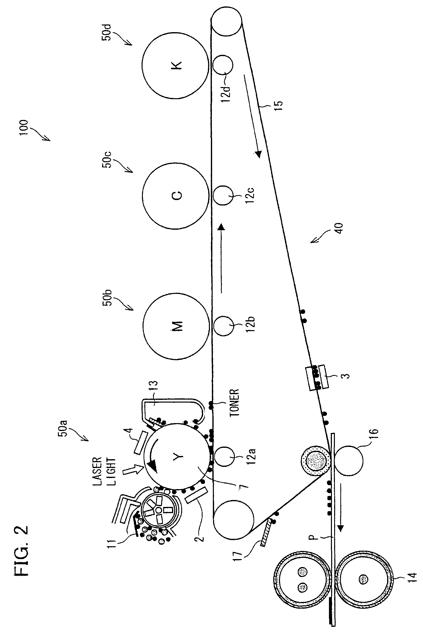
[0055]First, the following explains a whole arrangement of the image forming apparatus of the present embodiment. FIG. 2 is a cross sectional view schematically illustrating an arrangement of an image forming apparatus 100 including a pre-transfer charging device of the present embodiment. This image forming apparatus 100 is a tandem type printer employing an intermediate transfer system, and can form a full color image.

[0056]As illustrated in FIG. 2, the image forming appar...

example 1

[0111]The following description explains an Example which uses an ion generating element of the technology disclosed herein. Here, ion generating elements of Examples and Comparative Examples are explained with reference to FIGS. 1, 4, and 7.

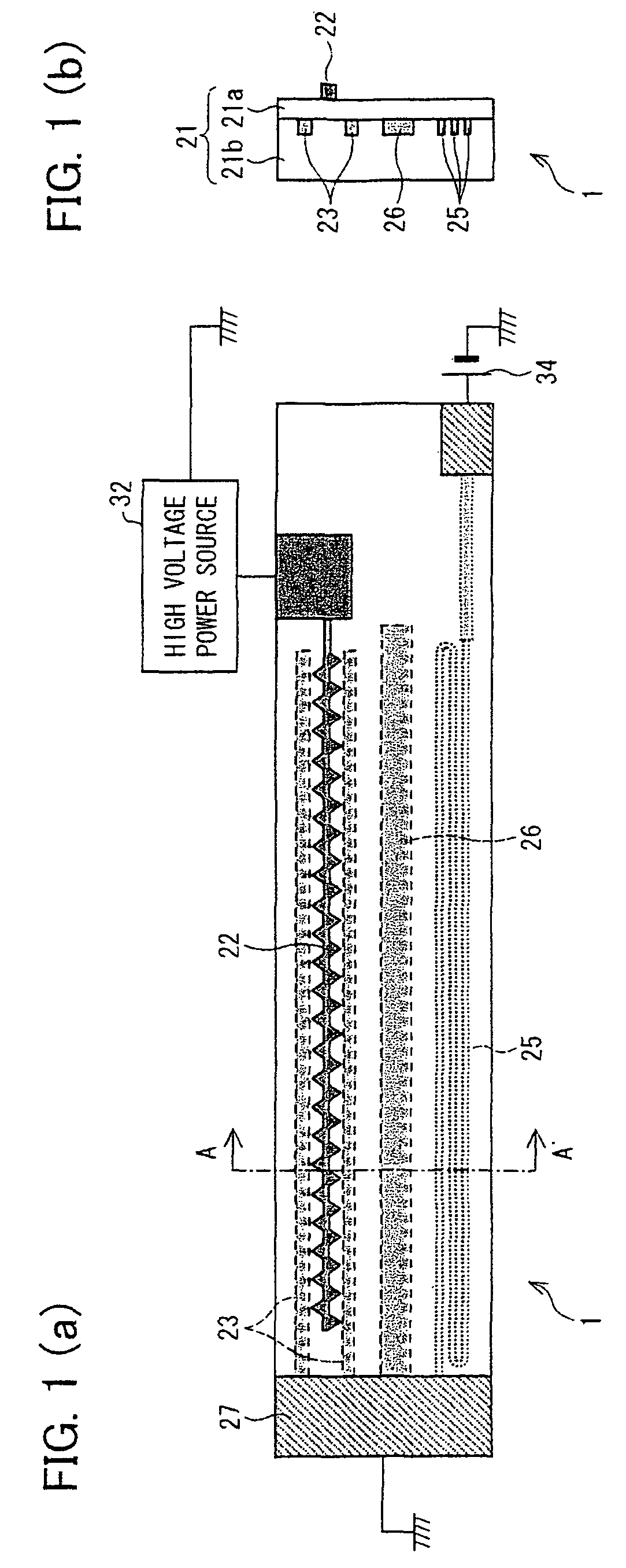
[0112]FIGS. 7(a) and 7(b) illustrate an ion generating element of a comparative example. In the ion generating element of Comparative Example 1 illustrated in FIG. 7(a), the inductive electrode 23 was line-shaped, and was bent in a U-shape so as to surround the discharge electrode 22. A bias voltage was applied to both ends of the inductive electrode 23 so that the inductive electrode 23 functioned as a heater. Namely, in Comparative Example 1, the inductive electrode 23 doubled as a heater electrode. In this Comparative Example 1, a width of the inductive electrode 23 was approximately 0.2 mm, a length thereof was approximately 600 (300×2) mm, and a resistance value thereof was approximately 30 Ω.

[0113]An ion generating element in Comparative E...

example 2

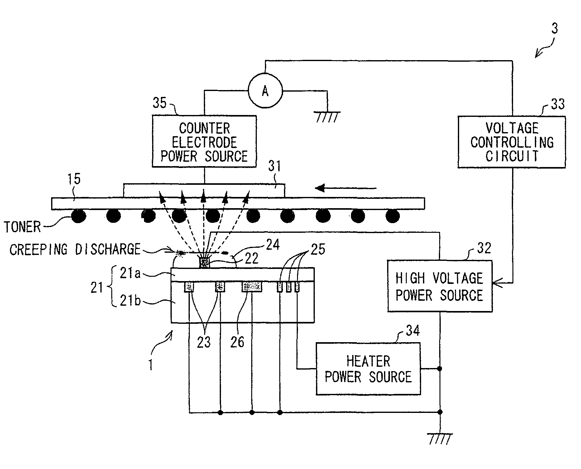
[0123]The following description explains another Example of an ion generating element according to the technology disclosed herein. As illustrated in FIG. 5, an ion generating element 1′ of the present Example (Example 2) included, in addition to the arrangement of the ion generating element 1, a shield electrode 26 in which both ends of the shield electrode 26 in a longitudinal direction each have a connection of ground. Each connection of ground was arranged to be connected with a ground potential. When the ion generating element 1 breaks, although an end section provided with the connection of ground of the shield electrode 26 (side with which the ground potential is connected) maintains a ground potential, an end section of the other side becomes in a floating state. In this case, the part that becomes in the floating state serves simply as a bridge electrode to a heater line. This gives a concern that the shield electrode 26 cannot function to shield the leak current. However, ...


PUM


Abstract

An ion generating element of the present invention includes a discharge electrode and an inductive electrode, both of which are provided so as to face each other with a dielectric body sandwiched therebetween, and a heater electrode which warms the ion generating element by Joule heat produced because of a passage of an electrical current. A distance between the discharge electrode and the heater electrode is larger than that between the discharge electrode and the inductive electrode, and further a shield electrode having a connection for ground is provided between the heater electrode and the inductive electrode on a surface of the dielectric body at a side on which the inductive electrode is provided. Hence, it is possible to prevent a leak to the heater electrode at low cost, while giving consideration towards safety.

Description

[0001]This Nonprovisional application claims priority under 35 U.S.C. §119(a) on Patent Application No. 2008-050644 filed in Japan on Feb. 29, 2008, and Patent Application No. 2008-146851 filed in Japan on Jun. 4, 2008, the entire contents of which are hereby incorporated by reference.[0002]1. Technical Field[0003]The technology disclosed herein relates to: an ion generating element, included in an image forming apparatus such as a copying machine, a printer, and a facsimile, for use in an image forming process in which an electrostatic latent image formed on an image bearing member is developed by toner and then transferred onto and fixed on a print medium; a charging device including the ion generating element; and an image forming apparatus including the ion generating element.[0004]More specifically, the technology disclosed herein relates to: an ion generating element, in which a discharge electrode and an inductive electrode are positioned on front and back sides of a dielectr...

Claims


Application Information

Patent Timeline
Patent Type & Authority Patents(United States)
IPC IPC(8): G03G15/02G03G15/16
CPCG03G15/0208G03G15/0291
Inventor ADACHI, KATSUMI
Owner SHARP KK
Why Eureka
Try Eureka