
Apparatus for installing pin to aligned guard/shaft assembly

Inactive Publication Date: 2011-11-15
HONDA MOTOR CO LTD
View PDF6 Cites 8 Cited by
  • Summary
  • Abstract
  • Description
  • Claims
  • Application Information

AI Technical Summary

Benefits of technology

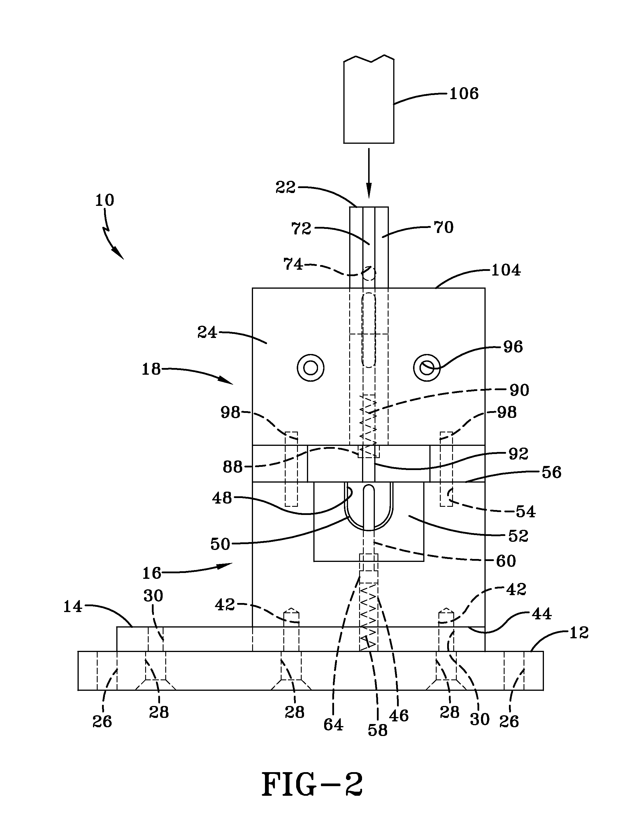
[0010]As a force is applied to the pin pusher, the pin pusher moves downward through the press head. The pin pusher arm extends into the pin guide and engages the pin for insertion. Upon engagement, the pin is forced downward into the vertically aligned apertures of the apertured shaft and aperture guard, which are locked in place by the press fixture. As the pin is inserted into the aligned apertures, the spring loaded alignment pin is forced into the press fixture. The mechanical stop halts the downward motion of the pin, ensuring a repeatably accurate pin insertion.
[0011]As described in more detail below, the design of the press block of the present invention assists with vertically aligning the apertured shaft and guard, and locks the apertured shaft and guard in place to minimize movement thereof during pressing. Therefore, an apparatus of the present invention overcomes the deficiencies of existing press blocks and pin insertion methods known by the inventor.

Problems solved by technology

Unfortunately, the devices and methods known to the inventor suffer from various deficiencies.
For example, known devices do not provide for a repeatably accurate pin insertion, nor do they provide the user with an easy means of aligning the shaft and guard for pin insertion.
It should also be realized that maintaining alignment of the shaft and guard during the pressing action can be difficult.
Specifically, the geometry of cylindrical bodies, such as an apertured shaft and corresponding apertured guard, makes it difficult to maintain alignment during press pin insertion.
Unfortunately, the inventor has observed that this difficulty in maintaining alignment often interferes with proper pin insertion into the shaft and guard and thus creates a nonexistent or ineffective attachment between the shaft and guard.

Method used


Image

  • Apparatus for installing pin to aligned guard/shaft assembly
  • Apparatus for installing pin to aligned guard/shaft assembly
  • Apparatus for installing pin to aligned guard/shaft assembly

Examples


Embodiment Construction

)

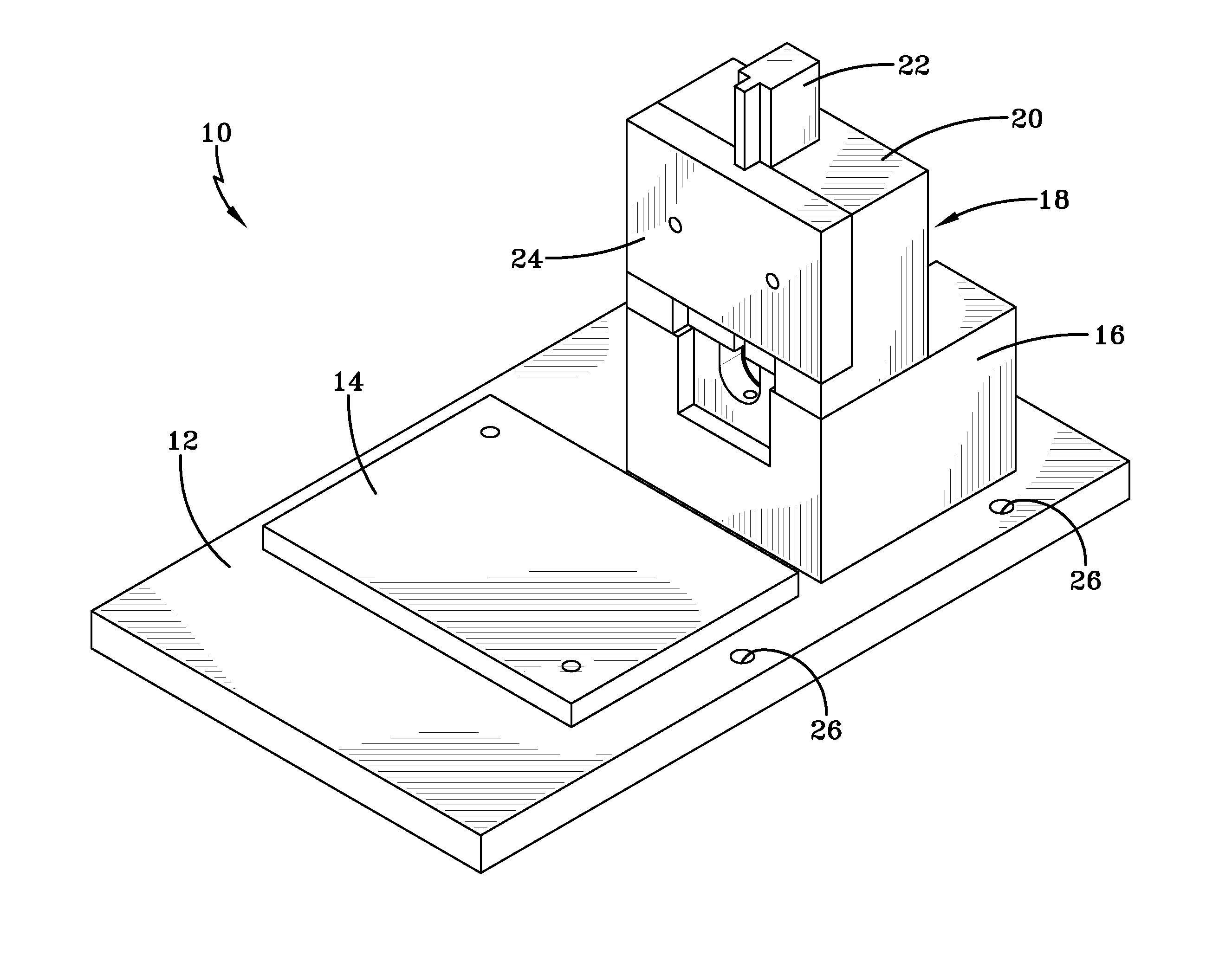
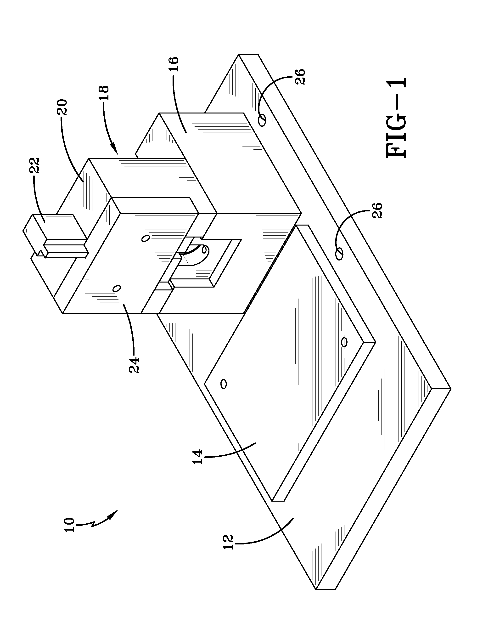
[0027]An exemplary press block 10 of the present invention is illustrated in FIG. 1, and is depicted in more detail in the rendered assembly view of FIG. 2 and in the component drawings of FIGS. 3-12. As shown, the press block 10 includes a mounting plate 12 having a mission plate 14 and a press fixture 16 attached to the top surface thereof. The press fixture 16 and the mission plate 14 are mounted adjacent one another on the mounting plate 12. A press head 18 is attached to the top surface of the press fixture 16. The press head 18 includes a pin block 20, a pin pusher 22, and a cover plate 24. The pin block 20 and cover plate 24 cooperate to slidably receive the pin pusher 22. Location apertures 26 are located in the mounting plate 12, the purpose of which is described in more detail below.

[0028]The mounting plate 12 of the exemplary press block 10 is depicted in FIG. 3. The mounting plate 12 includes a number of mounting apertures 28 through which the mission plate 14 and the p...


PUM

PropertyMeasurementUnit
Forceaaaaaaaaaa

Abstract

A device for inserting a pin into an apertured shaft having an apertured guard which includes a mission plate and an adjacent press fixture mounted to a mounting plate. The press fixture is adapted to receive and hold the apertured shaft and apertured guard. An alignment pin extends from the press fixture for insertion into the apertured shaft and apertured guard once the apertures in the shaft and guard have been vertically aligned. A press head is affixed atop the press fixture and adapted to insert a pin into the vertically aligned apertures of the apertured shaft and apertured guard.

Description

BACKGROUND OF THE INVENTIVE FIELD[0001]The present invention is directed to an apparatus for inserting a pin into at least one apertured member. More particularly, exemplary embodiments of the present invention are directed to an apparatus for inserting a pin into an apertured shaft having an apertured guard, wherein the apertured shaft and apertured guard are aligned to allow insertion of the pin therein.[0002]The attachment of guards, collars, or other like devices to a cylindrical body using a press-fit pin is well known in the art of engine, drive train, or other power equipment manufacturing. For example, a lawn mower transmission having an axle extending therefrom may have a guard placed around the axle to prevent grass or other foreign objects from entering the transmission.[0003]In a drive train manufacturing environment, such attachment of a guard to a shaft may occur in an assembly room or other like area. Because of the need to maintain a production pace, it must be ensur...

Claims


Application Information

Patent Timeline
IPC IPC(8): B23P19/10B25B27/00
CPCB25B27/04Y10T29/49895Y10T29/53796Y10T29/53961
Inventor MURPHY, BRIAN P.
Owner HONDA MOTOR CO LTD
Learn More