Connector insertion sensing structure

Inactive Publication Date: 2011-01-11
U D ELECTRONIC CORP
View PDF23 Cites 65 Cited by
  • Summary
  • Abstract
  • Description
  • Claims
  • Application Information

AI Technical Summary

Benefits of technology

[0009]To achieve this and other objects of the present invention, a connector insertion sensing structure comprises an electrically insulative housing, a sensing terminal mounted in a vertical front mounting groove on the front wall of the electrically insulative housing at one lateral side of at least one insertion hole of the electrically insulative housing, a metal shield surrounding the electrically insulative housing, and a metal actuation terminal extended from the fro

Problems solved by technology

Therefore, the arrangement of the network connector of a conventional desk computer or notebook computer does not facilitate installation of a modular cable.
However, if the computer is disposed in a cor

Method used


Image

  • Connector insertion sensing structure
  • Connector insertion sensing structure
  • Connector insertion sensing structure

Examples


Example

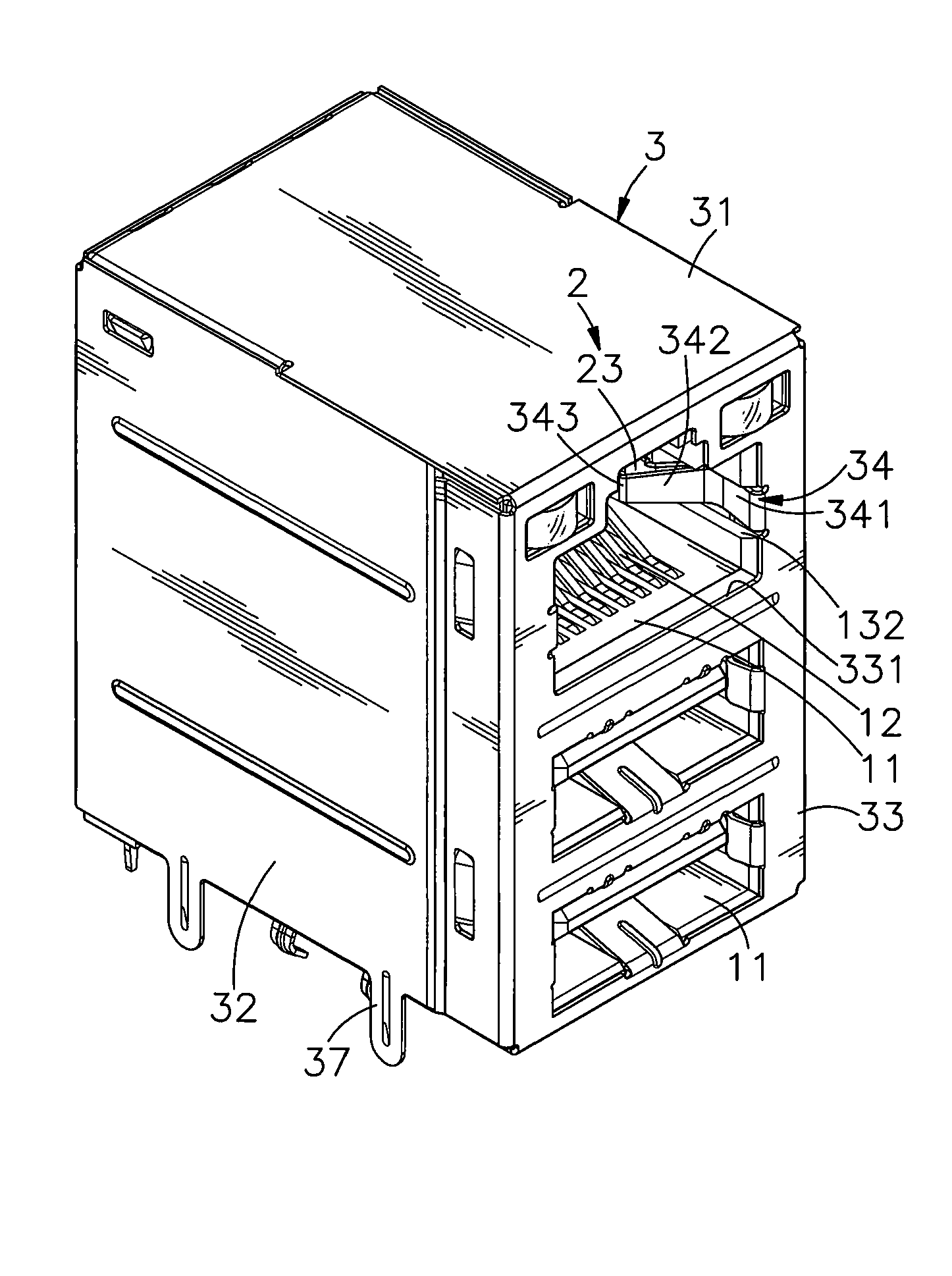
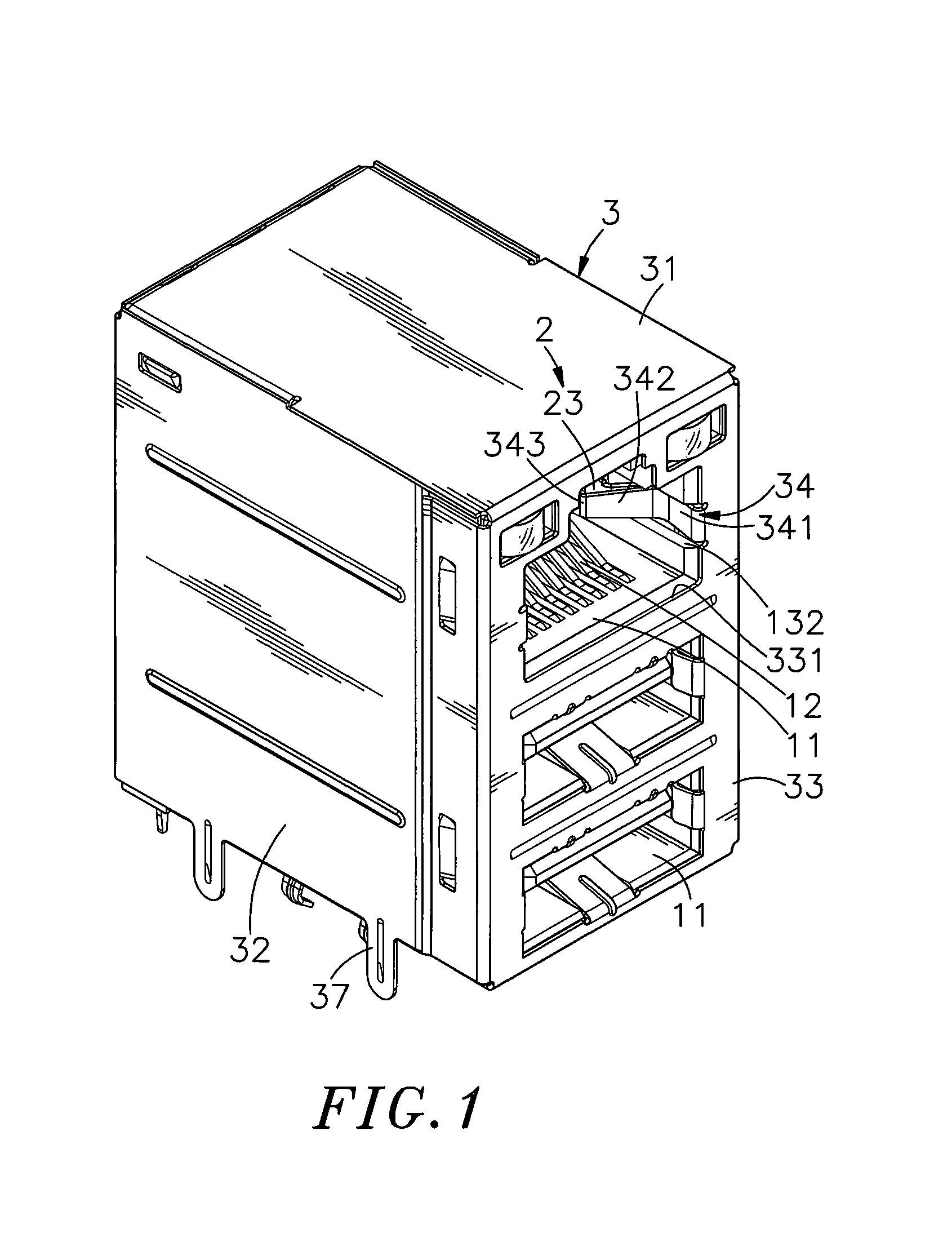
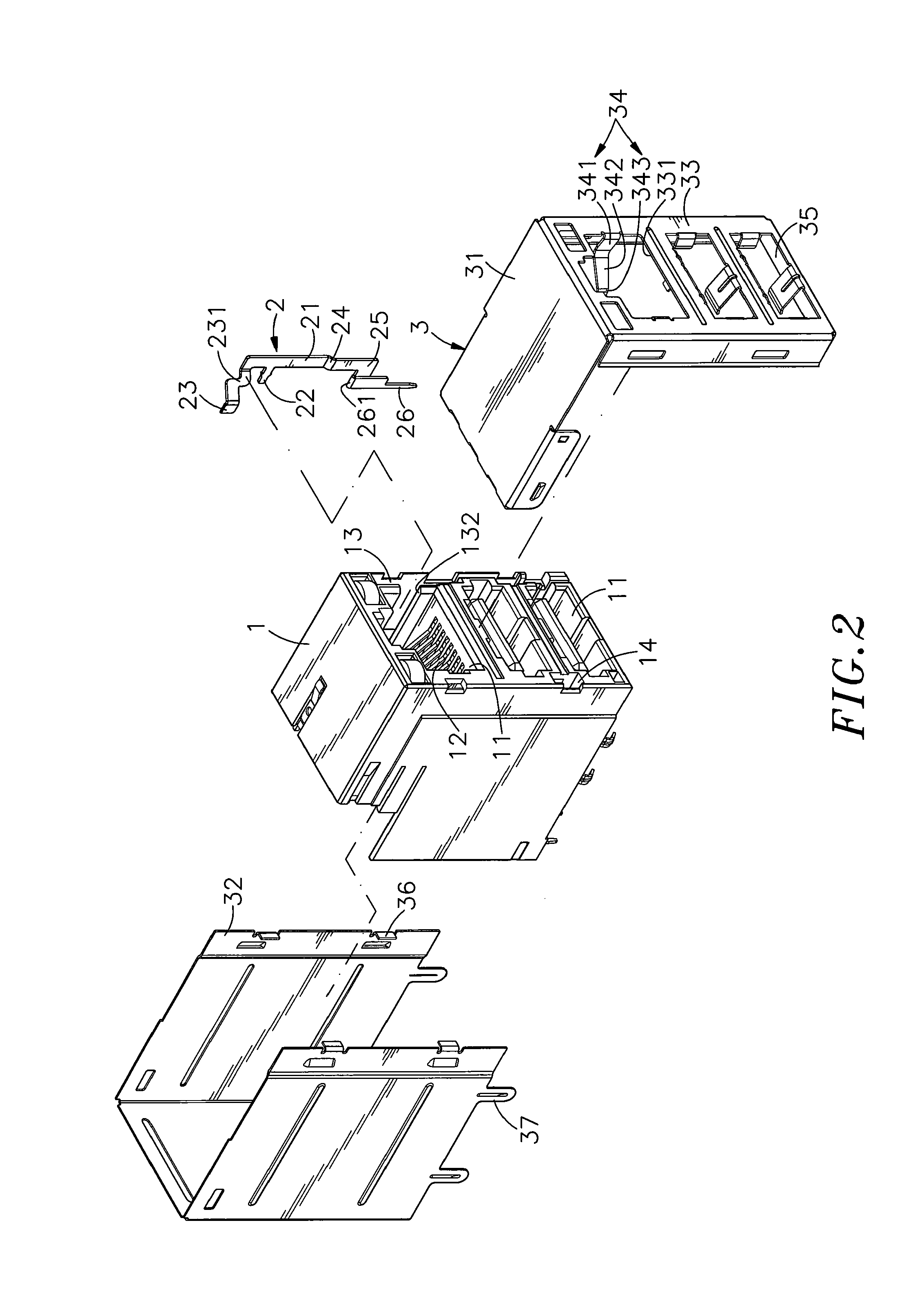
[0017]Referring to FIGS. 1˜3, a connector insertion sensing structure in accordance with the present invention is shown comprising an electrically insulative housing 1, a metal sensing terminal 2 and a metal shield 3.

[0018]The electrically insulative housing 1 comprises at least one insertion hole 11 cut through the front wall thereof for the insertion of an external modular plug 4 individually. According to the present preferred embodiment, the electrically insulative housing 1 comprises three insertion holes 11. Each insertion hole 11 has mounted therein a set of metal contacts 12 for the contact of respective metal contacts 41 of the inserted external modular plug 4. The electrically insulative housing 1 further comprises a vertical front mounting groove 13 located on the front wall at one lateral side relative to the insertion holes 11 and vertically extending through the bottom wall, a horizontal locating hole 131 perpendicularly extended from the vertical front mounting groove...


PUM


Abstract

A connector insertion sensing structure includes an electrically insulative housing having an insertion hole for the insertion of an external modular plug and a vertical front mounting groove located on the front wall at one lateral side of the insertion, a metal sensing terminal mounted in the vertical front mounting groove and having a contact portion suspending in the insertion hole and a bottom bonding tip for bonding to an external circuit board, and a metal shield surrounding the electrically insulative housing and having a metal actuation terminal backwardly extended from the front panel thereof and suspending in the insertion hole and movable by an inserted external modular plug to press a pressure tip thereof on the contact portion of the metal terminal in producing a signal indicative of the insertion of the external modular plug.

Description

BACKGROUND OF THE INVENTION[0001]1. Field of the Invention[0002]The present invention relates to electric connectors and more particularly, to a connector insertion sensing structure, which comprises a metal sensing terminal mounted in the electrically insulative housing thereof and a metal actuation terminal extended from the metal shield thereof and suspending in one insertion hole of the electrically insulative housing at one side for touching the metal sensing terminal to produce a signal upon insertion of an external modular plug into the insertion hole.[0003]2. Description of the Related Art[0004]Following fast development of computer technology, desk computers and notebook computers are popularly used by people in different fields in our society. Advanced computers commonly have high operation speed, small size and high mobility characteristics. Further, a computer has interface means with communication ports for the connection of peripheral apparatus, such as printer, mobile...

Claims


Application Information

Patent Timeline
IPC IPC(8): H01R3/00
CPCH01R13/65802H01R13/7031H01R27/02H01R24/62H01R13/6582
Inventor CHEN, PO-JUNG
Owner U D ELECTRONIC CORP
Why Eureka
Try Eureka