Upper structure for a shoe

a technology of upper body and shoe, which is applied in the direction of upper, fastening, bootlegs, etc., can solve the problems of hindering the free movement of the ankle, slack in the opening of the shoe, etc., and achieves the effect of enhancing the supportability of the upper body relative to the foot, and reducing the slack of the sho

Inactive Publication Date: 2011-11-15
MIZUNO CORPORATION
View PDF13 Cites 38 Cited by
  • Summary
  • Abstract
  • Description
  • Claims
  • Application Information

AI Technical Summary

Benefits of technology

[0010]According to the present invention, when wearing the shoe, by fastening the fastening member, the upper body presses against the calcaneus and talus of the foot via the outside upper member. Thereby, the heel portion of the foot can be held securely and thus a fit of the upper structure relative to the heel portion can be secured.
[0024]The shoe may have a heel counter member at the heel portion to improve supportability of the heel portion and in this case the expandable and contractible member of the upper body does not overlap with the heel counter member. Thereby, the expandable and contractible member of the upper body does not impede the action of the heel counter member.

Problems solved by technology

However, since the upper top portion in the prior-art shoe cannot contract in the longitudinal direction, the upper top portion is going to extend in the lateral direction thus causing a slack in the opening of the shoe.
However, fastening of the first and second strap may hinder a free motion of the ankle.

Method used


Image

  • Upper structure for a shoe
  • Upper structure for a shoe
  • Upper structure for a shoe

Examples


Embodiment Construction

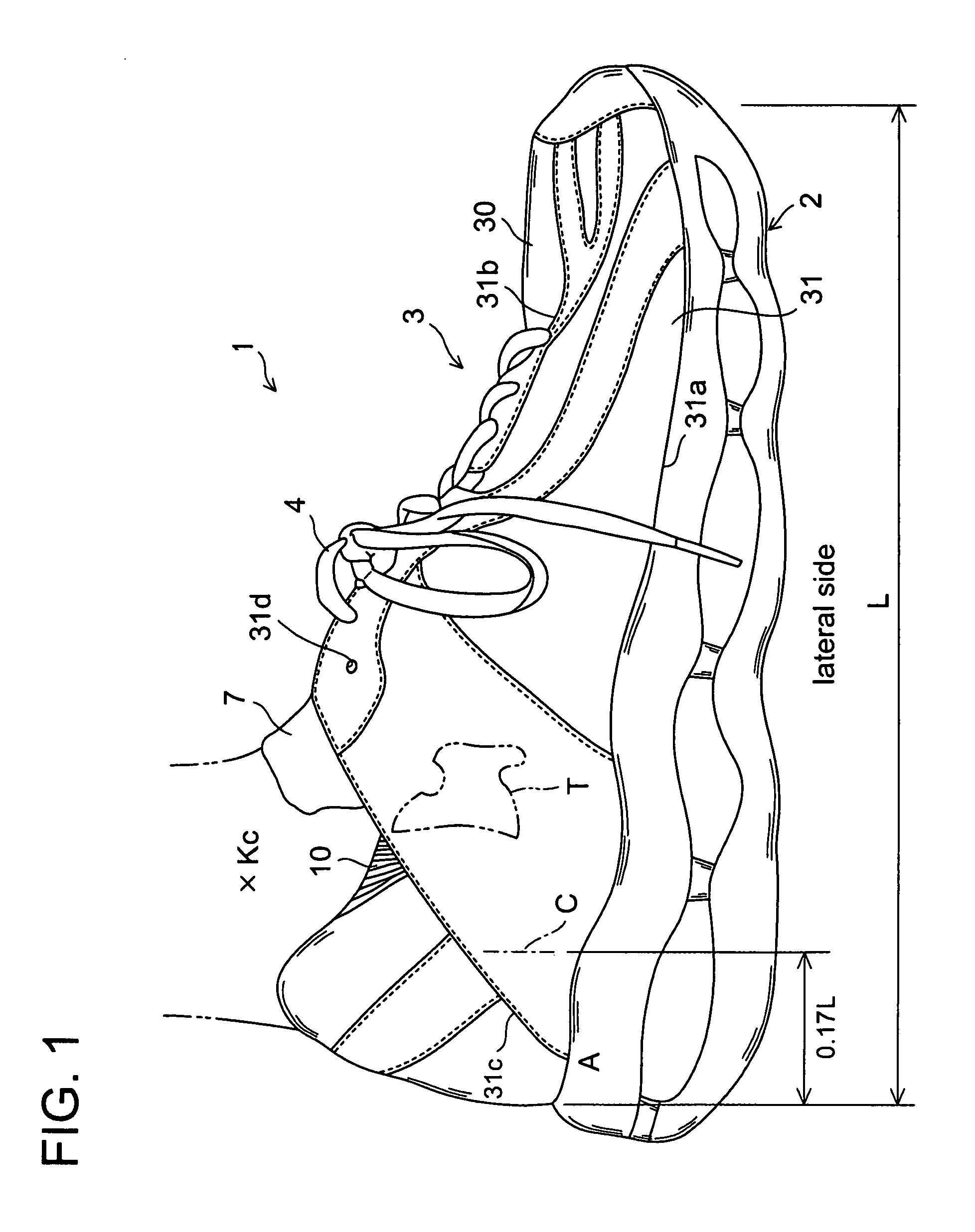
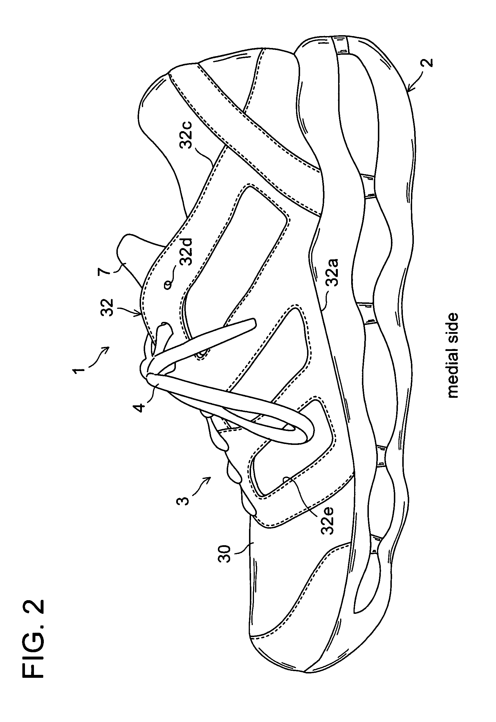
[0037]Referring now to the drawings, FIGS. 1 to 6 illustrate an upper structure for a shoe according to an embodiment of the present invention. In FIGS. 4 to 6, shoelaces are removed for illustration purposes.

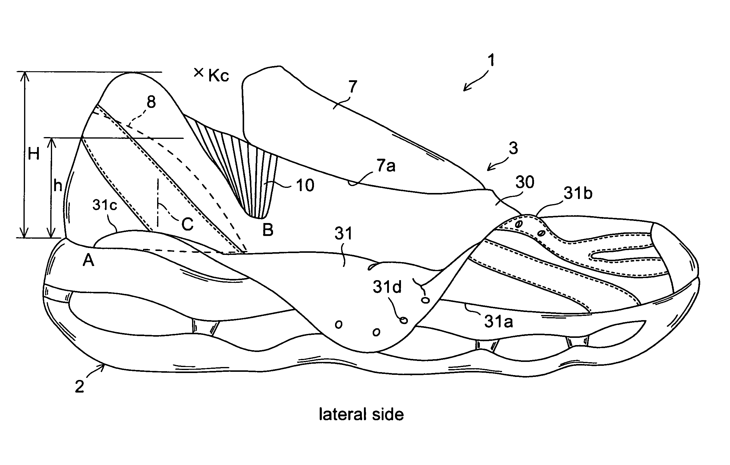
[0038]As shown in FIGS. 1 to 6, a shoe 1 is composed of a sole 2, and an upper assembly 3 fixedly attached on the top surface of the sole 2. The upper assembly 3 includes an upper body 30 provided inside the upper assembly 3 and covering a shoe wearer's foot, and an outside upper member 31 overlapping with the outside of the upper body 30 on the lateral side of the shoe 1.

[0039]The upper body 30 extends from the heel region through the midfoot region to the forefoot region of the shoe 1, and covers the heel portion, lateral and medial sides, and instep portion of the foot. The bottom surface of the upper body 30 is fixedly attached to the top surface of the sole 2.

[0040]The outside upper member 31 has an area that defines a bottom side edge portion 31a fixedly attached to the s...


PUM


Abstract

An upper structure for a shoe improves a fit of the heel portion during heel contact with the ground to the push off motion of a foot. The upper structure includes an upper body 30, and an outside upper member 31 that overlaps the lateral side of the upper body 30 to cover the talus T of the foot, and that has a bottom edge portion 31a fixedly attached to the bottom surface of the upper body 30. The rear end portion A of the bottom edge portion 31a is located rearwardly of the load centerline C of the calcaneus. A rear edge portion 31c of the outside upper member 31 is provided separately from the upper body 30 rearwardly of the talus T of the foot. An instep edge portion 31b of the outside upper member 31 is connected to the shoelace 4. On the lateral side of the heel portion of the upper body 30, there is a region 10 that is expandable and contractible in the longitudinal direction. The top end of the region 10 extends to the opening of the upper body 30 and the bottom end B of the region 10 is disposed in front of the load centerline C of the calcaneus and below a height h that corresponds to 55% of the lateral ankle height H of the foot.

Description

BACKGROUND OF THE INVENTION[0001]The present invention relates to an upper structure for a shoe, and more particularly, to an improvement in the structure for enhancing a fit of a heel portion of the shoe during heel contact of the shoe with the ground to the push off motion of the foot.[0002]A shoe is generally composed of a sole, an upper that is fixedly attached on the sole and that covers a foot of a shoe wearer, and a fastening member such as a shoelace that fastens the upper around the foot.[0003]Recently, in a running shoe, high-grade cushioning properties and ride feelings during running are required and thus at the time of deformation of the sole moderate elastic elongation is necessary on the top surface of the sole.[0004]In such a running shoe, when the shoe strikes onto the ground from the heel portion, in accordance with elongation of the sole top surface the bottom surface of the upper is also going to elongate in the longitudinal direction. As a result, the top portio...

Claims


Application Information

Patent Timeline
Patent Type & Authority Patents(United States)
IPC IPC(8): A43B23/00
CPCA43B13/181A43C1/00A43B23/0235A43B23/0275A43B23/047
Inventor SATO, NATSUKIYAMAMOTO, TETSUO
Owner MIZUNO CORPORATION
Why Eureka
Try Eureka