
Liquid gas vaporization and measurement system and method

a liquid gas and measurement system technology, applied in the field of liquid gas vaporization and measurement system and method, can solve the problems of insufficient domestic production and imports via pipeline from canada, the consumption of natural gas in the united states, and the inability to meet the demand, so as to achieve efficient flash vaporization of liquid gas

Active Publication Date: 2011-11-15
MUSTANG SAMPLING
View PDF10 Cites 28 Cited by
  • Summary
  • Abstract
  • Description
  • Claims
  • Application Information

AI Technical Summary

Benefits of technology

The present invention provides a system and method for efficiently and accurately sampling and measuring liquid gas. The system includes a transmission device for transmitting liquid gas, a measurement device for continuously extracting liquid gas from the transmission device, converting it into vapor form, and determining its constituent components. The device also includes an accumulator for storing the vapor gas and a heated regulator for controlling the pressure of the stored vapor gas. The method involves receiving liquid gas into a vaporizer, converting it into vapor gas, and accumulating it in a small storage device for further measurement. The invention improves the efficiency of liquid gas vaporization and measurement systems and addresses the problems of the prior art.

Problems solved by technology

Post-regulation, however, pipeline companies no longer purchase gas for resale.
Consumption of natural gas in the United States, however, has increased beyond the available supply of domestic natural gas.
Accordingly, domestic production combined with imports via pipeline from Canada will be insufficient to meet the demand.
Several problems arise from a system such as the one disclosed in Forster, however.
For example, the accuracy of the BTU measurement is unacceptable for today's standards.
These related art systems, however, also suffer from poor accuracy and / or high levels of maintenance.
This method of vaporization is very inefficient, however, and the accuracy of any resulting BTU measurements are unacceptable, e.g., less than 5 BTU, that is, the swing on the BTU measurement is greater than 5 BTU.

Method used


Image

  • Liquid gas vaporization and measurement system and method
  • Liquid gas vaporization and measurement system and method
  • Liquid gas vaporization and measurement system and method

Examples


Embodiment Construction

Exemplary, non-limiting, embodiments of the present invention are discussed in detail below. While specific configurations and dimensions are discussed to provide a clear understanding, it should be understood that the disclosed dimensions and configurations are provided for illustration purposes only. A person skilled in the relevant art will recognize that, unless otherwise specified, other dimensions and configurations may be used without departing from the spirit and scope of the invention.

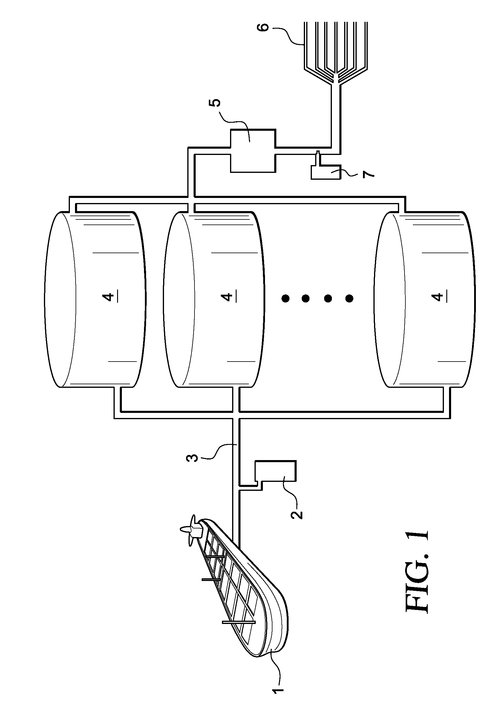
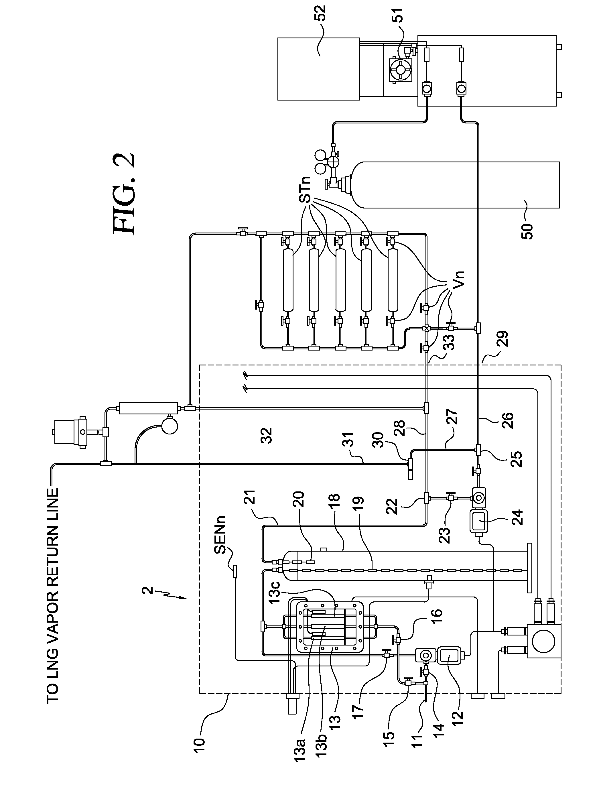
FIG. 1 is an exemplary block diagram illustrating a system in accordance with the present invention. As shown, the system of FIG. 1 comprises a tanker ship 1 carrying a shipment of liquefied natural gas (LNG). In accordance with this embodiment, tanker 1 docks into a port where the shipment of LNG is to be off-loaded to storage tanks before being regassified and shipped to various gas customers. According to the present embodiment tanker ship 1 is a marine vessel. However, a skilled artisan wo...


PUM

PropertyMeasurementUnit
diameteraaaaaaaaaa
temperaturesaaaaaaaaaa
lengthaaaaaaaaaa

Abstract

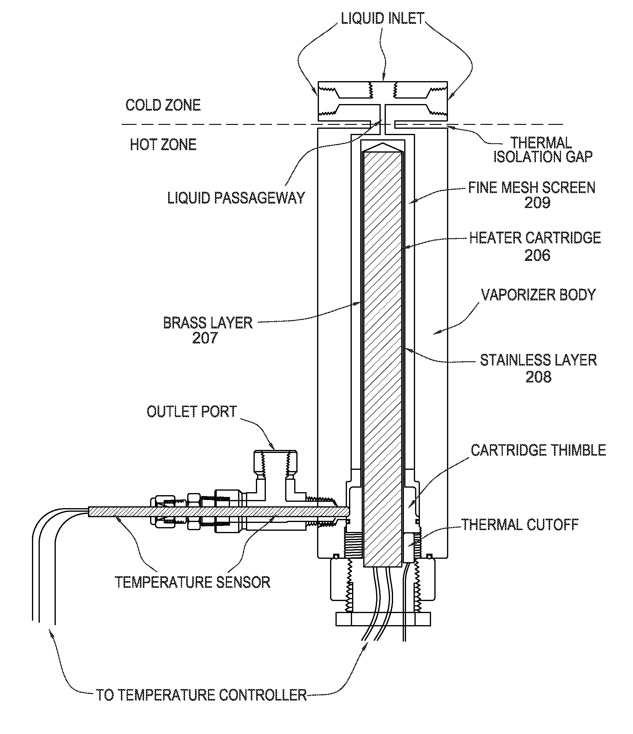
A liquid gas vaporization and measurement system, and associated method, for efficiently vaporizing a continuous sample of liquid gas, such as liquid natural gas (LNG), and accurately determining the constituent components of the gas. A constant flow of liquid gas sampled from a mass storage device is maintained in a vaporizing device. Within the vaporizing device the liquid gas is flash vaporized within heated narrow tubing. The liquid gas is converted to vapor very quickly as it enters one or more independently operating vaporizer stages within the vaporizing device. The vapor gas is provided to a measuring instrument such as a chromatograph and the individual constituent components and the BTU value of the gas are determined to an accuracy of within + / −0.5 mole percent and 1 BTU, respectively.

Description

II. FIELD OF THE INVENTIONThis invention relates generally to a system and method for the efficient vaporization and measurement of liquid natural gas (LNG). More particularly, the invention relates to a system and method for continuously and efficiently vaporizing an LNG shipment, or portion thereof, into its gaseous form in order to accurately determine the constituent components and British Thermal Unit (BTU) value of the LNG shipment.III. BACKGROUND OF THE INVENTIONNatural gas is a combustible, gaseous mixture of several different hydrocarbon compounds and is typically extracted from deep underground reservoirs formed by porous rock. The composition of natural gas extracted from different reservoirs varies depending on the geographic location of the reservoir. In fact, it is not entirely uncommon for the composition of gas extracted from a single given reservoir to vary to an extent. Regardless of any variations, however, the primary component of natural gas is methane, a colorl...

Claims


Application Information

Patent Timeline
Patent Type & Authority Patents(United States)
IPC IPC(8): G01N1/00
CPCF17C6/00F17C13/02G01N1/10G01N1/22F17C9/00G01N2001/2261F17C2221/033F17C2223/0161F17C2223/033F17C2223/046F17C2225/0123F17C2225/0161F17C2225/033F17C2225/035F17C2227/0135F17C2227/0302F17C2227/0311F17C2227/0318F17C2227/0332F17C2227/0393F17C2250/0447F17C2250/0456F17C2260/024F17C2265/05F17C2265/061F17C2270/0105F17C2270/0136F17C2270/0171G01N33/22G01N33/225G01N2001/105G01N2030/8854G01N30/16G01N2030/126H05B3/44H05B2203/021
Inventor THOMPSON, KENNETH O.GREHOLD, WALTER F.
Owner MUSTANG SAMPLING
Learn More