
Sequential injection gas guns for accelerating projectiles

a gas gun and projectile technology, applied in the direction of compressed gas guns, weapons, white arms/cold weapons, etc., can solve the problems of inability to maintain, the initial gas pressure decreases rapidly, and the shot is not controlled,

Inactive Publication Date: 2011-11-15
BATTELLE ENERGY ALLIANCE LLC
View PDF8 Cites 9 Cited by
  • Summary
  • Abstract
  • Description
  • Claims
  • Application Information

AI Technical Summary

Benefits of technology

[0008]In an additional embodiment, a method of accelerating a projectile through a gas gun comprises positioning a projectile longitudinally between an injection port and another injection port within the bore of the barrel. A first pressurized gas volume is injected into the bore through the first injection port to accelerate the projectile and propel the projectile down the barrel past the second injection port. Additionally, a second pressurized gas volume is injected into the barrel through the second injection port after passage of the projectile thereby to further accelerate the projectile and propel the projectile down the barrel toward a muzzle end of the barrel.

Problems solved by technology

This is because the initial gas pressure decreases rapidly and cannot be maintained as the projectile travels down barrel.
When using conventional gas guns, the shot is not controlled beyond the initiation of a primary stage and if an undesirable projectile acceleration is occurring within the gun barrel it cannot be corrected during the shot.
As a consequence, obtaining a desired projectile velocity generally involves trial and error.

Method used


Image

  • Sequential injection gas guns for accelerating projectiles
  • Sequential injection gas guns for accelerating projectiles
  • Sequential injection gas guns for accelerating projectiles

Examples


Embodiment Construction

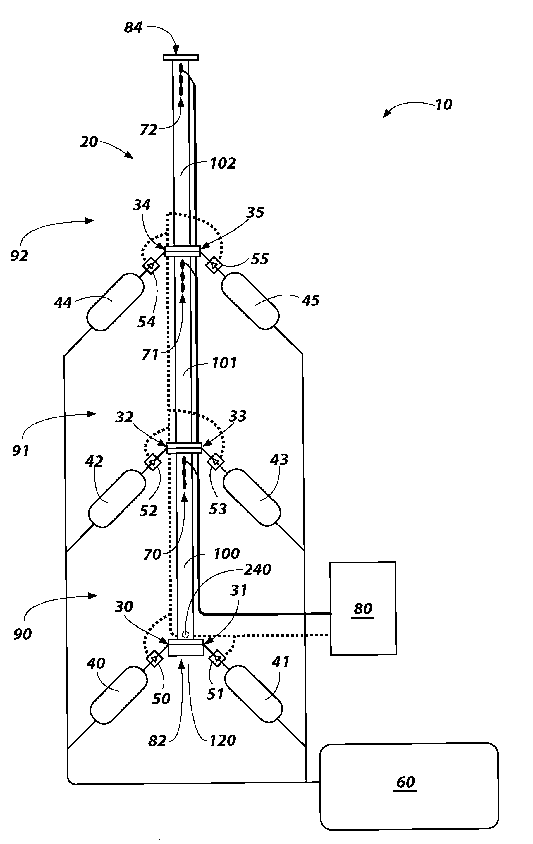
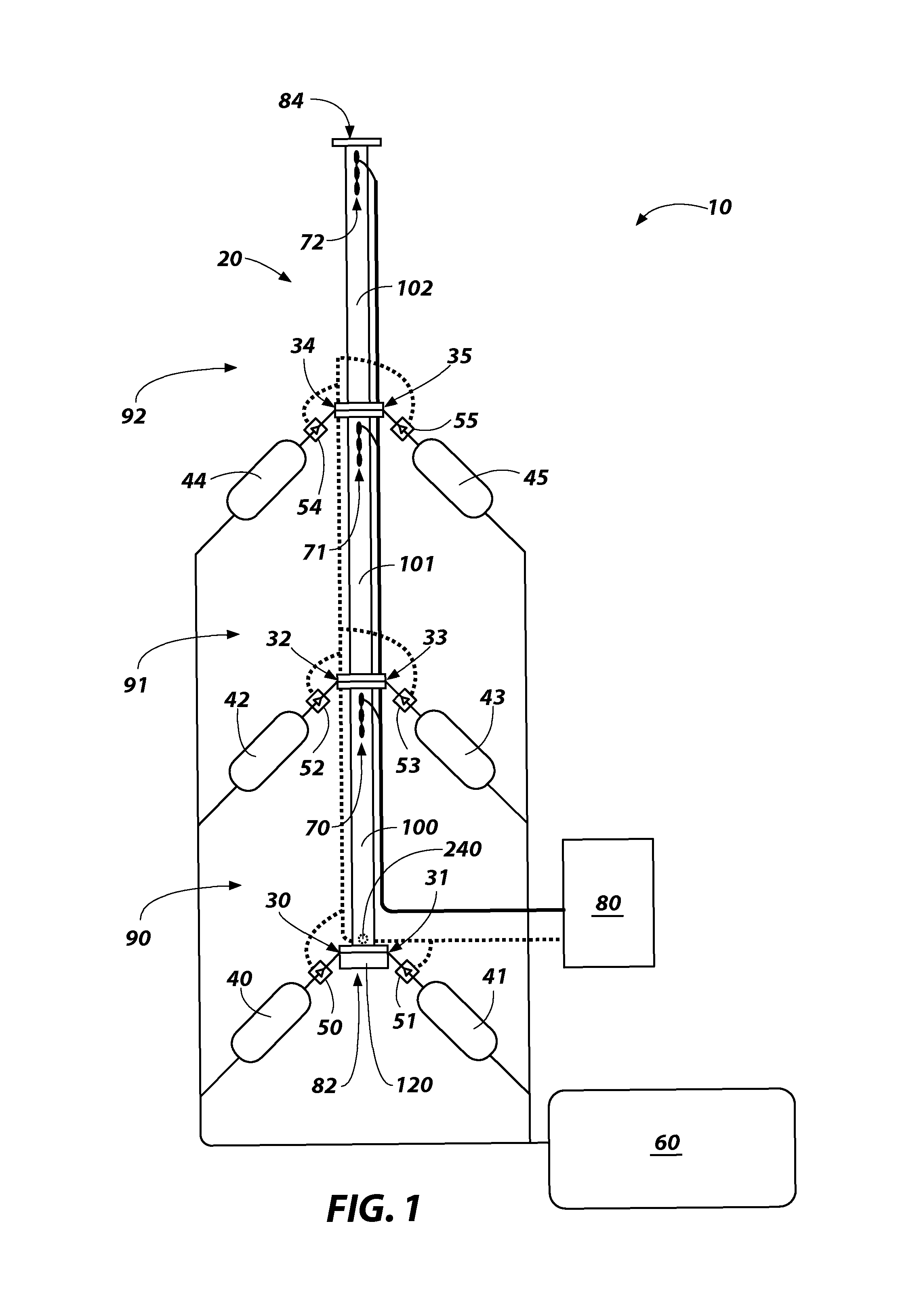
[0013]A gas gun 10 is shown in FIG. 1 that includes a barrel 20 with a bore having a plurality of injection ports 30-35 opening thereinto, each injection port, designated variously at 30-35 in respective fluid communication with a source of pressurized gas such as a pressure vessel, designated variously at 40-45 through an associated valve, designated variously at 50-55. The gas gun 10 may additionally include a primary pressure supply 60 in selective communication with and to charge pressure vessels 40-45, one or more projectile velocity sensors 70-72 and a control module 80.

[0014]The barrel 20 includes a breech end 82, where a projectile may be positioned in preparation for launching, and a muzzle end 84, where the projectile may exit the barrel 20 upon launching. The barrel 20, having a plurality of injection ports 30-35, includes a first injection port 30 and a second injection port 32. The first injection port 30 is located at, or at least proximate to, the breech end 82 of the...


PUM


Abstract

Gas guns and methods for accelerating projectiles through such gas guns are described. More particularly, gas guns having a first injection port located proximate a breech end of a barrel and a second injection port located longitudinally between the first injection port and a muzzle end of the barrel are described. Additionally, modular gas guns that include a plurality of modules are described, wherein each module may include a barrel segment having one or more longitudinally spaced injection ports. Also, methods of accelerating a projectile through a gas gun, such as injecting a first pressurized gas into a barrel through a first injection port to accelerate the projectile and propel the projectile down the barrel past a second injection port and injecting a second pressurized gas into the barrel through the second injection port after passage of the projectile and to further accelerate the projectile are described.

Description

GOVERNMENT RIGHTS[0001]This invention was made with government support under Contract No. DE-AC07-05-ID-14517 awarded by the United States Department of Energy. The government has certain rights in the invention.TECHNICAL FIELD[0002]The present invention relates to sequential injection gas guns and methods for accelerating projectiles through such gas guns. More particularly, embodiments of the invention relate to gas guns having a first injection port located proximate a breech end of a barrel and a second injection port located longitudinally between the first injection port and a muzzle end of the barrel. Embodiments of the invention also relate to modular gas guns that include a plurality of modules, wherein each module may include a barrel segment having one or more injection ports. Additional embodiments of the invention include methods of accelerating a projectile through a gas gun, such as injecting a first pressurized gas into a barrel through a first injection port to acce...

Claims


Application Information

Patent Timeline
IPC IPC(8): F41F1/00F41B11/62
CPCF41B11/62
Inventor LACY, JEFFREY M.CHU, HENRY S.NOVASCONE, STEPHEN R.
Owner BATTELLE ENERGY ALLIANCE LLC
Learn More