
Surface-mounted crack detection

a sensor and surface technology, applied in the direction of instruments, non-metal conductors, conductors, etc., can solve the problems of high risk of cracking on certain parts of structural surfaces, labor-intensive tests, and time-consuming

Inactive Publication Date: 2011-11-15
NAT RES COUNCIL OF CANADA
View PDF11 Cites 18 Cited by
  • Summary
  • Abstract
  • Description
  • Claims
  • Application Information

AI Technical Summary

Problems solved by technology

Frequently due to loading conditions and stress concentrations, certain parts of structural surfaces are known to have a higher risk of cracking than others.
Cracks caused or assisted by fluctuating loading, degradation of a composition, etc. are significant problems in a wide variety of areas.
Such tests are therefore labour intensive, and time consuming, and can only be run during working hours.
Unfortunately, such apparatus does not work effectively.
A problem with this approach is that the tape has to be physically applied to the surface, which due to its brittle nature, is susceptible to cracking on installation.
It may be impossible or exceedingly difficult to apply such a tape to uneven test surfaces.
Moreover, in our experience, stick on layers have bonding problems, and if a circuit peels, it cannot sense a crack underneath it.
Furthermore the electrical test circuit, which is expected to break when a crack forms in some situations may reconnect when the crack closes, failing to raise alarms in some cases, or requiring more expensive sampling equipment for reliable detection, if reliable detection is possible.
Such sampling equipment may be larger, and may require a power supply.
It may be difficult to continue sampling the system while it is in use because of obstructions, etc.

Method used


Image

  • Surface-mounted crack detection
  • Surface-mounted crack detection
  • Surface-mounted crack detection

Examples


example

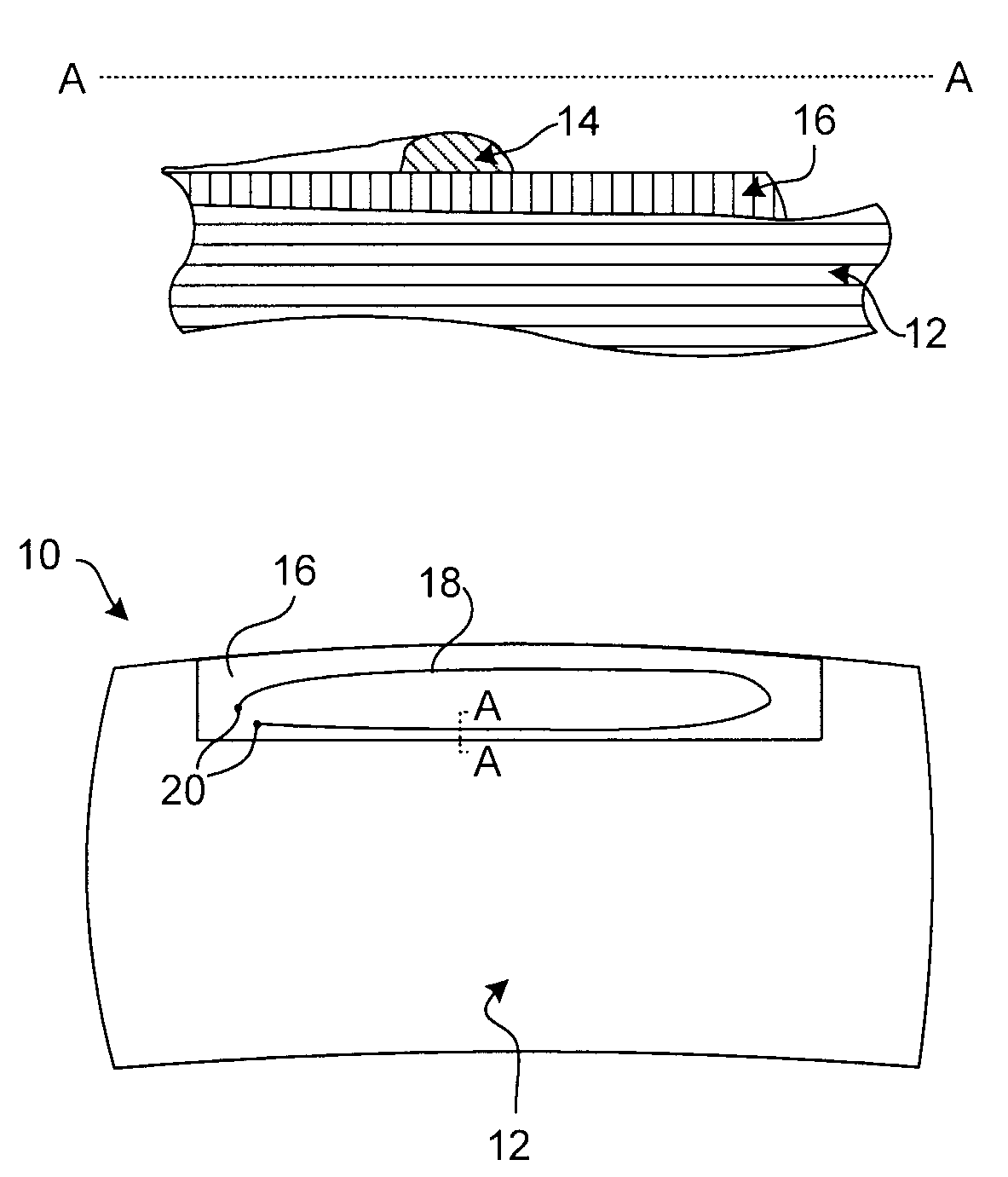
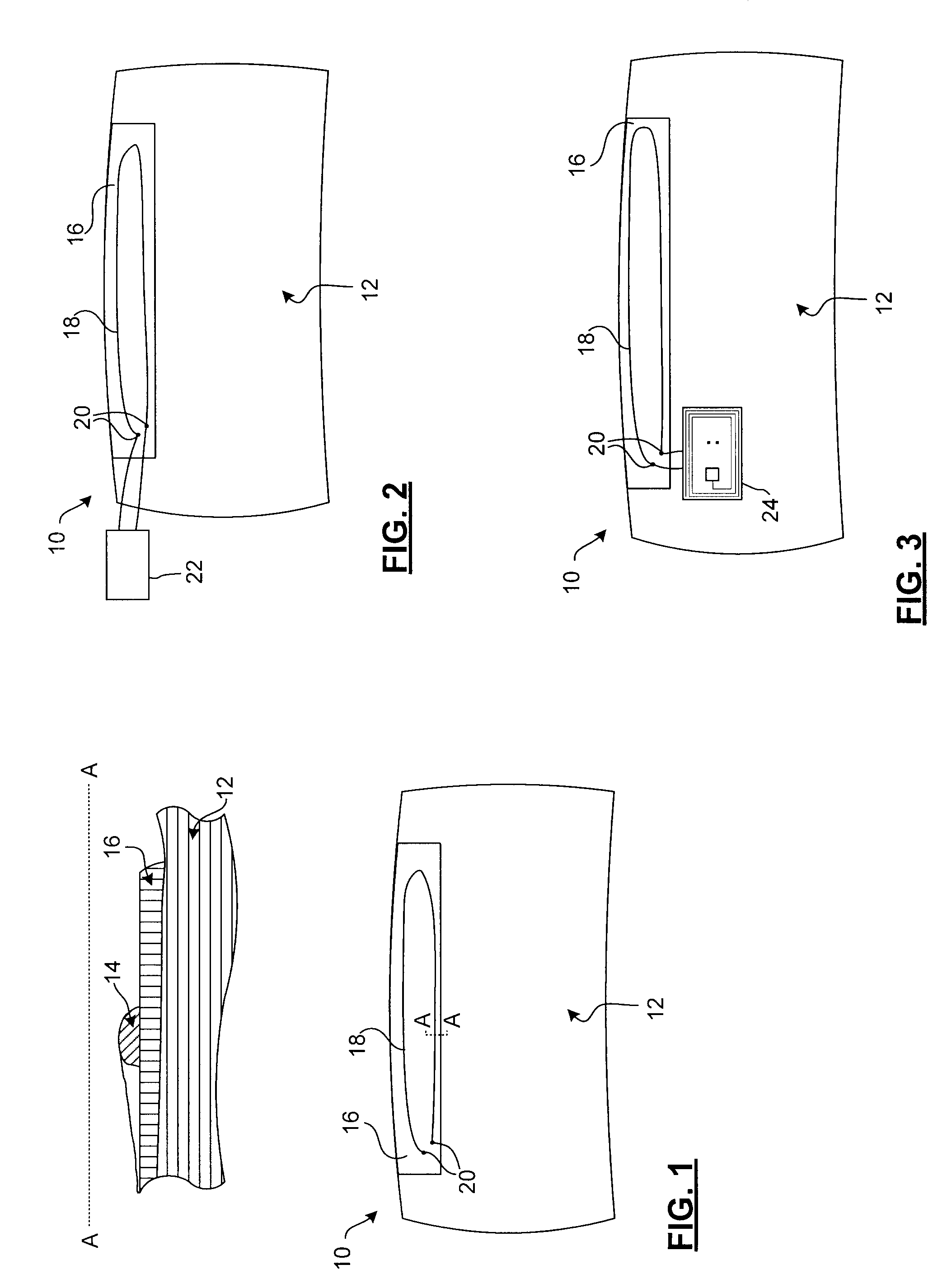
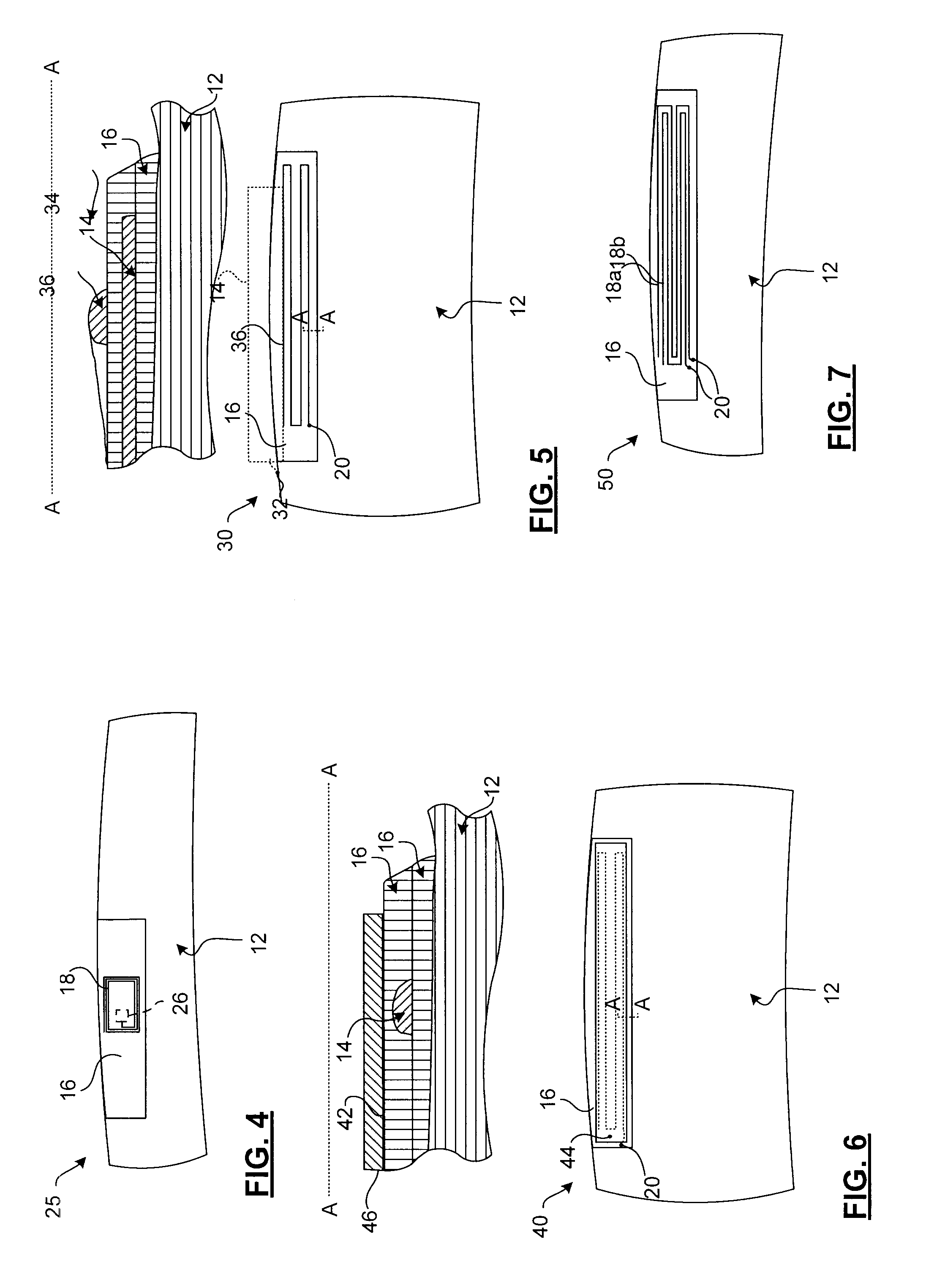
[0070]The circuit diagram shown in FIG. 10 was used to verify the principle of the invention. The sensing circuit used a 10-volt DC power supply, which was connected to an analogue input of a computerized MTS load frame controller. The MTS load frame controller can be set to “alarm” (notify the operator by displaying a warning message) or autonomously “halt” a command program sequence immediately upon detecting a pre-set change in the signal on the analogue input circuit. When the voltage on the analog input dropped below 9 volts, the MTS load frame controller halted the test and stopped the cyclic loading. A lap joint shown in FIG. 11 stopped after 280,000 cycles.

[0071]FIG. 11 is an image of a riveted, lap jointed, aluminum test coupon upon which a surface-mounted crack detection apparatus has been affixed. The undercoat was a manually painted on layer of Omega CC™ high temperature ceramic-based cement. The undercoat was found to be about 5 / 1000ths of an inch thick. The electricall...


PUM

PropertyMeasurementUnit
percent elongationaaaaaaaaaa

Abstract

A cementitious compound provides a brittle undercoat for making a surface-mounted crack sensor on a surface. A low percent elongation and low tensile strength of the cementitious compound have proven valuable in ensuring that cracks in the underlying surface are transmitted through the undercoat so that a trace of conductive ink or paint on the undercoat more reliably detects the crack.

Description

CROSS-REFERENCE TO RELATED APPLICATIONS[0001]This application is a national entry of International Application PCT / CA2006 / 001549 filed Sep. 20, 2006, and claims the benefit of U.S. Provisional application Ser. No. 60 / 762,158 filed Jan. 26, 2006.BACKGROUND OF THE INVENTION[0002]This invention relates in general to the field of non-destructive testing, and in particular to the detection of cracks on a surface using a surface-mounted sensor.[0003]In many mechanical and civil devices, structures are used for mechanical supports that are susceptible to cracking. Frequently due to loading conditions and stress concentrations, certain parts of structural surfaces are known to have a higher risk of cracking than others. Cracks caused or assisted by fluctuating loading, degradation of a composition, etc. are significant problems in a wide variety of areas. The testing of materials, bonds between materials, and components under environmental and stress conditions is often used to determine sa...

Claims


Application Information

Patent Timeline
Patent Type & Authority Patents(United States)
IPC IPC(8): G08B21/00G01B7/16C04B35/04C04B35/10C04B35/14C04B35/48G01N22/02
CPCG01N27/24
Inventor MARINCAK, ANTON
Owner NAT RES COUNCIL OF CANADA
Learn More