Check patentability & draft patents in minutes with Patsnap Eureka AI!

System and method for forecasting the composition of an outbound train in a switchyard

a technology of switchyard and outbound train, which is applied in the direction of position/direction control, railway tracks, registering/indicating, etc., can solve the problems of significant financial penalties, significant financial repercussions for the railroad operator, and delays incurring significant financial penalties

Active Publication Date: 2011-11-15
CANADIAN NAT RAILWAY CO
View PDF132 Cites 11 Cited by
  • Summary
  • Abstract
  • Description
  • Claims
  • Application Information

AI Technical Summary

Benefits of technology

The system enhances operational efficiency by predicting railcar availability, reducing delays and financial penalties by automating the assignment of railcars to departure trains, ensuring timely departures and improved network performance.

Problems solved by technology

However, it also brings constraints.
Such occurrence may create a cascading effect throughout entire segments of the railroad network and have significant financial repercussions for the railroad operator.
Specifically, it is not uncommon for an operator to guarantee railcar arrival times to customers and delays incur financial penalties that may be significant.

Method used


Image

  • System and method for forecasting the composition of an outbound train in a switchyard
  • System and method for forecasting the composition of an outbound train in a switchyard
  • System and method for forecasting the composition of an outbound train in a switchyard

Examples


Embodiment Construction

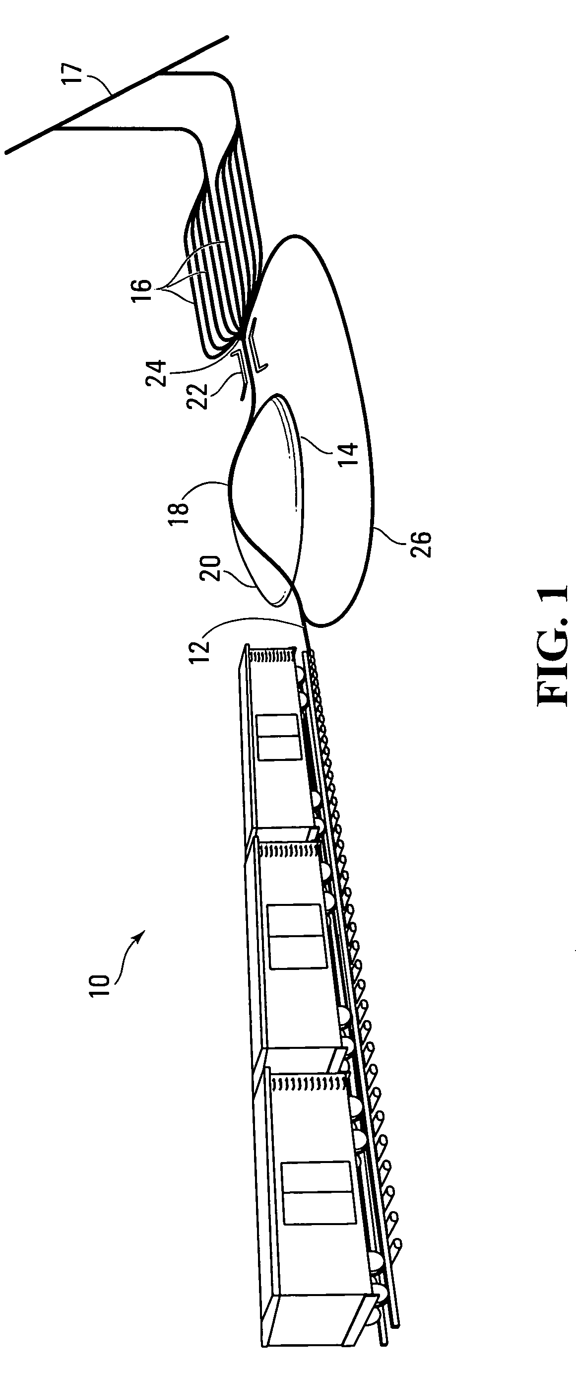
[0042]FIG. 1 is an illustration of a hump switching yard in which the management process of the invention can be implemented. The hump switching yard 10 has four main components namely receiving tracks 12, a hump 14, classification tracks 16 and departure tracks 17. The receiving tracks 12 include railway sections in which an incoming train delivers railcars to be switched.

[0043]The receiving tracks 12 lead to the hump 14. The hump 14 includes a set of tracks 20 that lead to the hump crest 18 that is the highest elevation of the hump 14. railcars are pushed by a locomotive on the tracks 20 up to the hump crest 18 at which point the railcar rolls down the hump 14 by gravity toward the set of classification tracks 16. The railcar passes through retarders 22 that will reduce its speed allowing it to gently coast in anyone of the selected classification tracks 16. A track switch 24, located downstream the retarders 22 temporarily connects the hump track 12 to a selected one of the class...


PUM


Abstract

A system for forecasting the outbound workload in a switchyard. The system has a processing entity for which receives information on railcar traffic for handling by the switchyard, wherein the railcar traffic includes railcars that are yet to be switched into classification tracks of the switchyard. For every departure train of two or more departure trains, the processing entity applies logic rules to the information to compute a forecast of railcar traffic that will be available to the departure train for transport out of the switchyard. An output releases data derived from the forecast of railcar traffic, describing the traffic available for each train of the two or more departure trains.

Description

CROSS-REFERENCE TO RELATED APPLICATION[0001]The present application is a continuation-in-part of prior U.S. application Ser. No. 11 / 601,338 filed on Nov. 17, 2006. The contents of the aforementioned document are incorporated by reference herein.[0002]This application is also a continuation-in-part application claiming the benefit of priority under 35 USC §120 of U.S. patent application Ser. No. 11 / 387,347 filed Mar. 23, 2006 by Kari Muinonen et al., and presently pending, which claims the benefit of priority on U.S. provisional application Ser. 60 / 754,601 filed Dec. 30, 2005, now abandoned. The contents of the above-mentioned patent application are incorporated herein by reference.FIELD OF THE INVENTION[0003]The invention relates to a process for managing operations in a railroad switchyard. The invention also encompasses a technological platform and individual components thereof to implement the process.BACKGROUND OF THE INVENTION[0004]A railroad network normally contains one or mo...

Claims


Application Information

Patent Timeline
Patent Type & Authority Patents(United States)
IPC IPC(8): G05D1/00G05D3/00
CPCB61L17/00B61L17/02G06Q10/0631
Inventor MUINONEN, KARIMORENCY, VINCENTBARKER, MATTHEW
Owner CANADIAN NAT RAILWAY CO
Features
  • R&D
  • Intellectual Property
  • Life Sciences
  • Materials
  • Tech Scout
  • Unparalleled Data Quality
  • Higher Quality Content
  • 60% Fewer Hallucinations
Learn More