Eureka AIR delivers breakthrough ideas for toughest innovation challenges, trusted by R&D personnel around the world.

Cache Configuration in a Database System

a database system and configuration technology, applied in the field of cache configuration in a database system, can solve the problems of affecting the performance of the system, the size of the cache memory, the fragmentation of the cache fragment, etc., and the change of the system

Inactive Publication Date: 2008-03-20
IBM CORP
View PDF10 Cites 254 Cited by
  • Summary
  • Abstract
  • Description
  • Claims
  • Application Information

AI Technical Summary

Benefits of technology

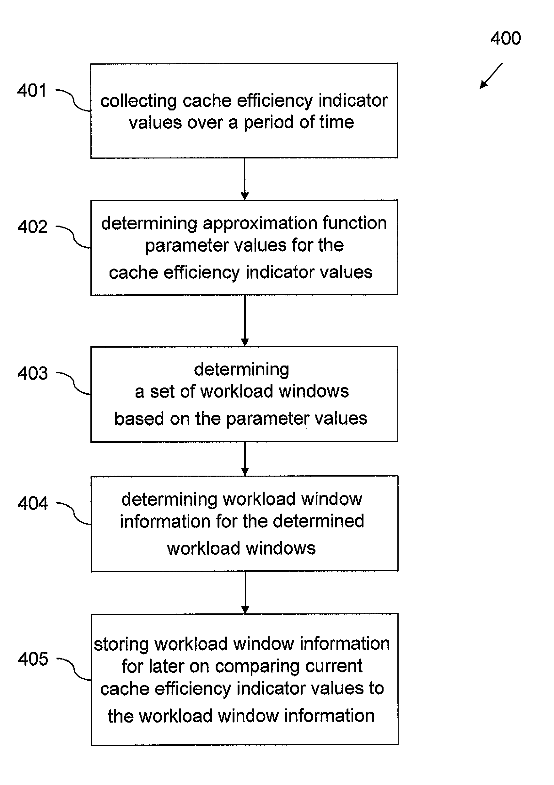
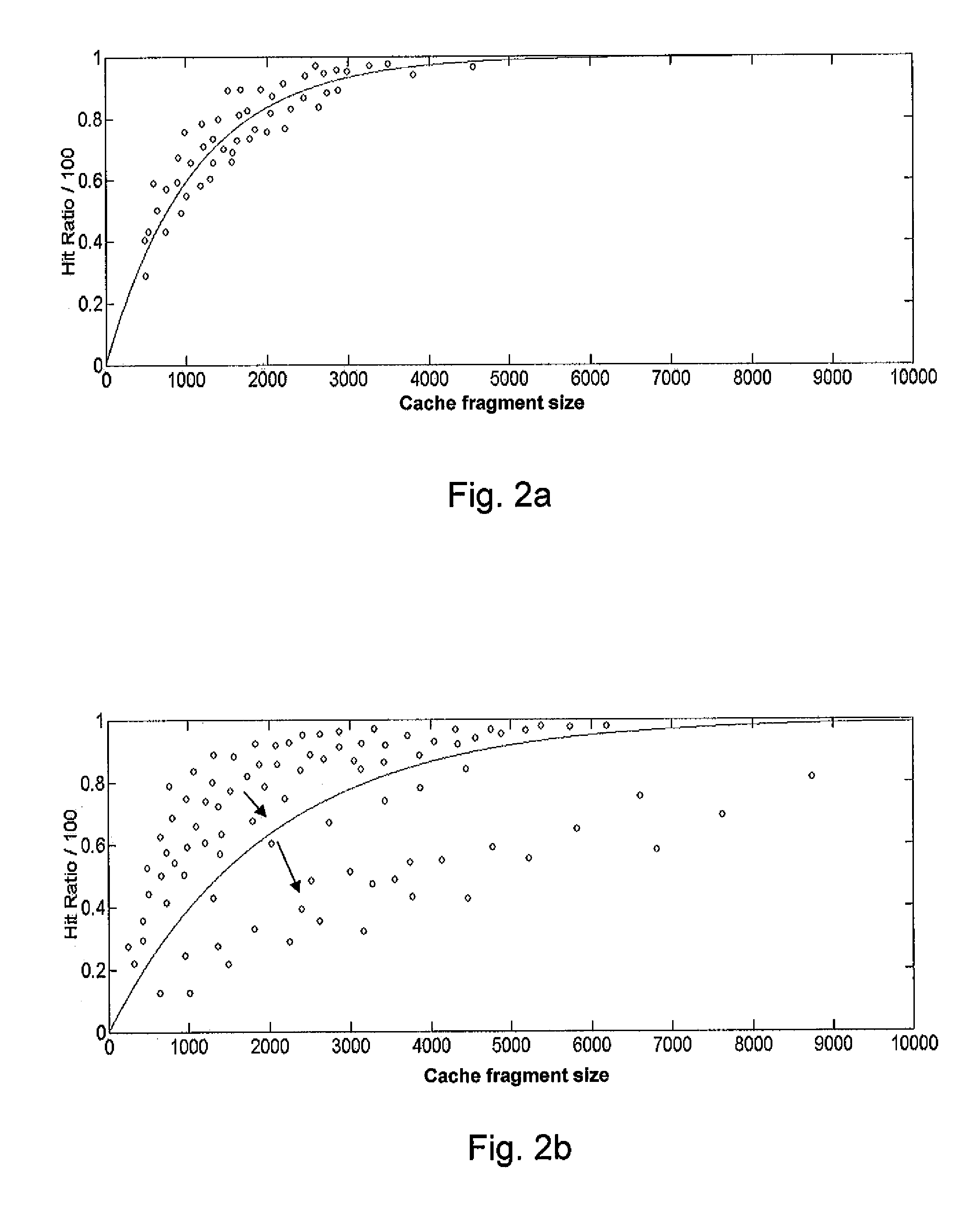
[0012]A first aspect of the present invention provides a computer-implemented method for constructing workload windows in a database system having at least one cache fragment. The method comprises collecting cache-efficiency-indicator values of the at least one cache fragment during operation of the database system over a period of time. The method also comprises providing a plurality of approximation-function-parameter values for the collected, cache-efficiency-indicator value and an approximation function representing a relation between a cache-efficiency

Problems solved by technology

Currently, setting up data caching in a database cache memory is difficult.
The drawback of this solution is that the size of the cache memory, its fragmentation, i.e. the number of cache fragments, and also the size of the individual cache fragments has to be adjusted manually.
Changing sizes of the cache memory and / or of the cache fragments can result in changes in a system's performance.
As such, in a following cycle, those changing might be counterproductive and therefore the aforementioned method is not applicable to improve performance of database systems.
The first option normally takes hours to process on a workstation, which makes it difficult for a desirable, automatic-continuous-background optimization.
The later option depends upon multiple factors and must be performed for all objects and statements in the database (e.g. tables, Materialized Query Tables (MQTs), index and the like), which makes it normally impossible for continuous manual optimization.
Even if a Data Base Administrator (DBA) has constructed a suitable configuration, the database workload alternates and changes frequently, which results in poor system throughput.

Method used


Image

  • Cache Configuration in a Database System
  • Cache Configuration in a Database System
  • Cache Configuration in a Database System

Examples


Embodiment Construction

[0027]The following description is presented to enable one having ordinary skill in the art to make and use the embodiment and is provided in the context of a patent application and the generic principles and features described herein will be apparent to those skilled in the art. Thus, the present embodiment is not intended to be limited to the embodiments shown, but is to be accorded the widest scope consistent with the principles and features described herein.

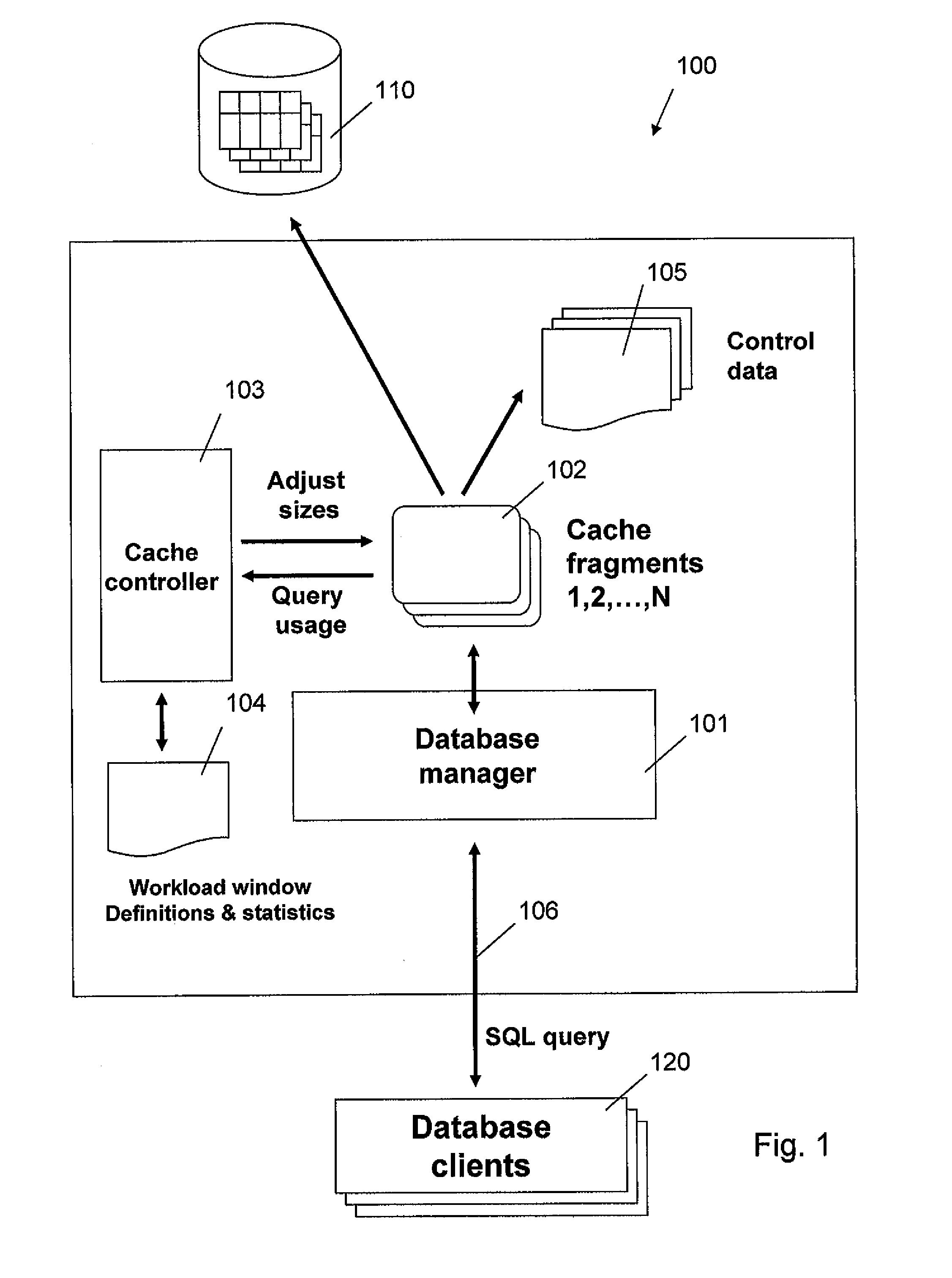
[0028]In the following description and the appended claims, a cache may be divided into a set of sub-parts. The term “cache fragment” refers to such a sub-part of the cache. The cache may be arranged into one or more sub-parts. In the case of one subpart, the cache fragment refers to the whole cache. Typically there is a certain upper limit for the cache size, and the term “cache configuration” refers to adjusting the total size of the cache and / or to adjusting the sizes of the cache fragments within a given total cache size....


PUM


Abstract

A computer-implemented method is disclosed. The method includes collecting cache-efficiency-indicator values of an at least one cache fragment during operation of a database system over a period of time. Providing approximation-function-parameter values for the collected, cache-efficiency-indicator values, an approximation function representing a relation between a cache-efficiency-indicator and the size of a respective cache fragment. The method continues by providing a set of workload windows based on the approximation-function-parameter values. Next, providing a workload-window information for the set of workload windows, the workload-window information including at least one approximation-function-parameter value representing each determined workload window. The method further includes storing the workload-window information for a comparison based on current, cache-efficiency-indicator values and the workload-window information.

Description

CROSS-REFERNCE TO RELATED APPLICATIONS[0001]Under 35 U.S.C. 119(e), this application claims the benefit of priority to DE Applications No. 06120936.7, filed on Sep. 20, 2006.FIELD OF THE INVENTION[0002]The present invention relates generally to cache configuration in a database system.DESCRIPTION OF RELATED ART[0003]The usage of a database system may change very significantly over a period of time. For example, the database usage changes typically over 24 hours due to typical user activities during working times and to batch jobs for mass data processing during the night. To achieve preferably optimal system throughput, an internal cache of the database system should be adapted to the respective currently executed workload.[0004]Caches are structures which keep data in memory after the data is currently no longer in use, which avoids having to recreate or reload data from a disc if the data is reused. Typical caches in a database are built to cache application data in database table...

Claims


Application Information

Patent Timeline
IPC IPC(8): G06F12/00
CPCG06F2212/601G06F12/0802
Inventor KARN, HOLGERMILLER, SVEN
Owner IBM CORP
Why Eureka
Eureka Blog
Learn More