
Function generation circuit

Active Publication Date: 2008-01-10
PANASONIC SEMICON SOLUTIONS CO LTD
View PDF7 Cites 12 Cited by
  • Summary
  • Abstract
  • Description
  • Claims
  • Application Information

AI Technical Summary

Benefits of technology

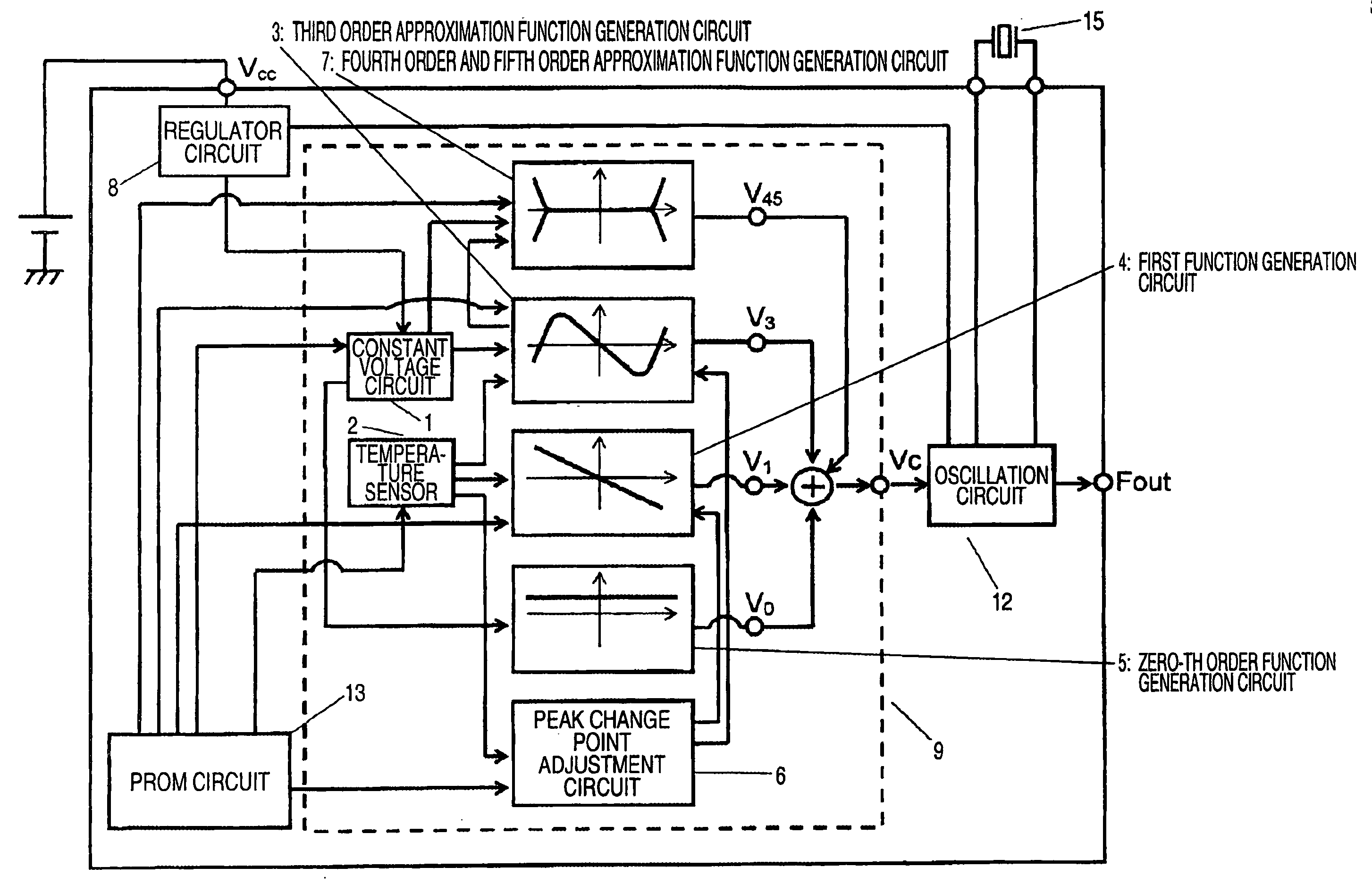
[0027] According to the arrangement of the first aspect of the invention, the third order approximation function generation circuit can generate control signals by dividing the range into the first to the m-th temperature domain. Therefore, since the number of temperature domains m is increased, control signals can be generated by accurately performing the third order function approximation within a broad temperature area.
[0030] According to the arrangement of the first aspect of the invention, the fourth order and fifth order approximation function generation circuit employs the g-th control signal and the h-th control signal, both of which are output by the third order approximation function generation circuit in consonance with the g-th temperature range and the h-th temperature range, respectively. Therefore, the peak change point used by the fourth order and the fifth order approximation function generation circuit can be adjusted, in common, by the peak change point adjustment circuit, and the increase in the circuit size can be prevented.

Problems solved by technology

However, since the conventional quartz oscillation apparatus equipped with a temperature compensation function employs A / D conversion to obtain a crossover approximation for generation of a control voltage used for temperature compensation, a quantized noise occurs, and essentially, a frequency skipping problem can not be avoided.
Further, since a clock signal generation circuit is required, there is a problem with the mixing of clock noise, and a problem in that, when power is on, it takes time for an oscillated frequency to be stabilized because of a time constant for a sample holding circuit 115A.
Therefore, an adjustment error occurs.

Method used


Image

  • Function generation circuit
  • Function generation circuit
  • Function generation circuit

Examples


first embodiment

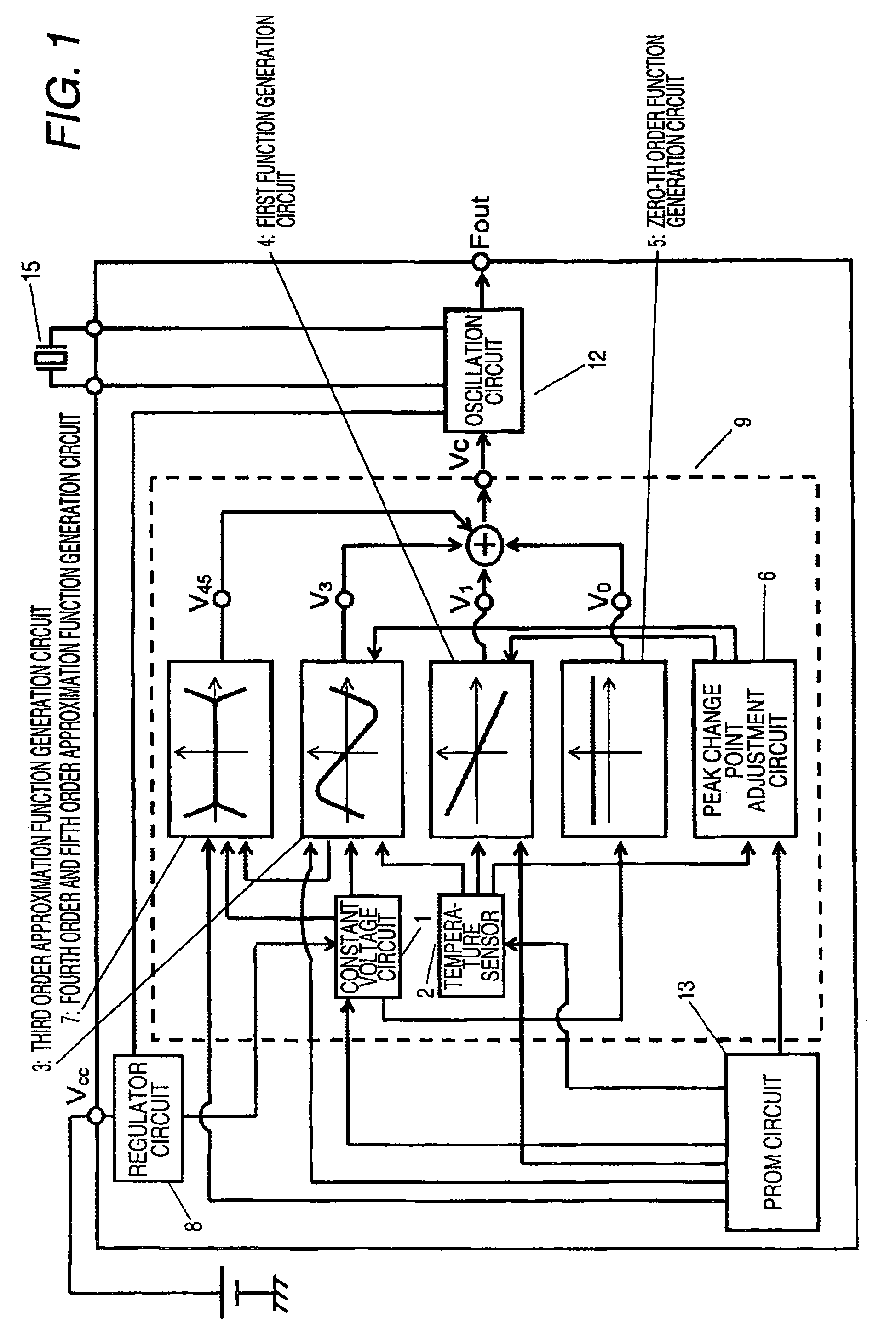
[0089]FIG. 1 is a diagram for explaining a function generation circuit according to a first embodiment of the present invention. In this embodiment, the function generation circuit, indicated by a broken line, serves as a temperature compensation circuit 9. While referring to FIG. 1, a constant voltage circuit 1 receives a control signal from a regulator circuit 8, and generates an analog signal that is not affected by an ambient temperature. While a temperature sensor circuit 2 outputs an analog signal that is affected by the ambient temperature.

[0090] A third order approximation function generation circuit 3 receives signals from the constant voltage circuit 1 and the temperature sensor circuit 2, and generates a third order approximation function control signal V3 that corresponds to a third order temperature characteristic parameter. A first order function generation circuit 4 receives a signal from the temperature sensor circuit 2, and generates a first order function control ...

second embodiment

[0143]FIG. 13A is a diagram for explaining a function generation circuit according to a second embodiment of the present invention. In FIG. 13A, a constant voltage circuit 1 receives a control signal from a regulator circuit 8 and generates an analog signal that is not affected by the ambient temperature. A temperature sensor circuit 2 outputs an analog signal that is affected by the ambient temperature.

[0144] A third order approximation function generation circuit 3 receives signals from the constant voltage circuit 1 and the temperature sensor circuit 2 and generates a third order approximation function control signal V3 that is consonant with a third order temperature characteristic parameter. And a first order function generation circuit 4 receives a signal from the temperature sensor circuit 2 and generates a first order function control signal V1 that is affected by the ambient temperature.

[0145] A zero-th order function generation circuit 5 receives a signal from the consta...

third embodiment

[0152]FIG. 16 is a diagram showing an example n-th order approximation function generation circuit for a function generation circuit according to a third embodiment of the present invention. When, as shown in FIG. 16B, three contiguous temperature domains TL1, TL2 and TL3 are arranged by dividing a low temperature area, an amplification circuit 162 generates a first order function control signal consonant with a first order temperature characteristic parameter for the domain TL1; an amplification circuit 163 generates a first order function control signal consonant with a first order temperature characteristic parameter for the domain TL2; and an amplification circuit 164 generates a first order function control signal consonant with a first order temperature characteristic parameter for the domain TL3.

[0153] When the control signals output by the amplification circuits 162, 163 and 164 are added together, a low-temperature side control signal VnL, of a control signal Vn that appro...


PUM


Abstract

A first order function generation circuit receives a signal from a temperature sensor circuit, and generates a fist order function control signal V1 that is affected by the ambient temperature. A fourth order and fifth order approximation function generation circuit receives signals from the temperature sensor circuit and from the third order approximation function generation circuit, and generates a fourth and fifth order approximation function control signal V45 that is affected by the ambient temperature. A peak change point adjustment circuit outputs a signal to adjust the value of a peak change point temperature Ti for the third order approximation function generation circuit, the first order generation function circuit and the fourth order and fifth order approximation function generation circuit. A temperature compensation circuit adds together control signals V0, V1, V3 and V5, and outputs the resultant signal Vc.

Description

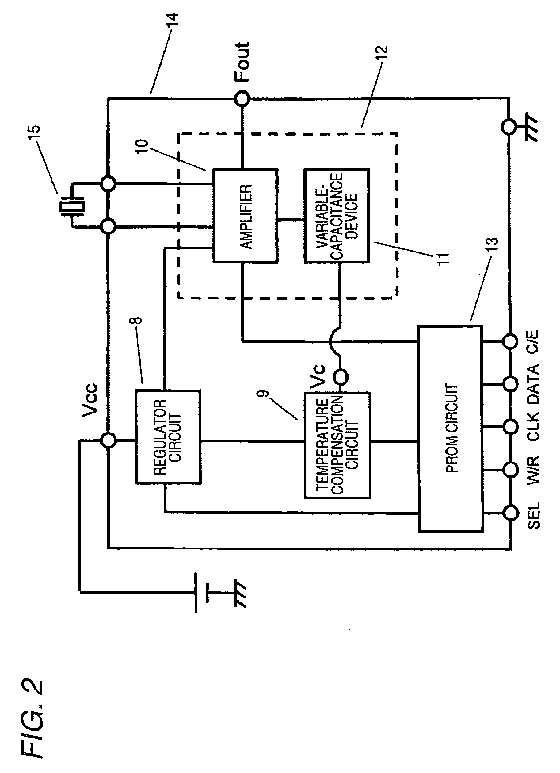
BACKGROUND OF THE INVENTION [0001] 1. Field of the Invention [0002] The present invention relates to a function generation circuit, employed for a temperature-compensating quartz oscillation circuit that employs a quartz oscillation frequency, an electronic apparatus and a communication apparatus. [0003] 2. Description of the Related Art [0004] Recently, the demand for portable electronic apparatuses has increased remarkably, and for such electronic apparatuses, compact, accurate quartz oscillators that generate reference clock signals are requisites. [0005] As the temperature characteristics, the oscillation frequency of a quartz oscillator included in a quartz oscillation apparatus has the third and first order temperature elements due to a crystal unit that is employed for a quartz oscillator. Specifically, when as shown in FIG. 17A the horizontal axis represents an ambient temperature Ta and the vertical axis represents an oscillation frequency f, the characteristic of the oscil...

Claims


Application Information

Patent Timeline
IPC IPC(8): H03L1/02
CPCH03L1/022
Inventor NAGATOMO, KEITAKEUCHI, HISATOSHINGU, KEIGO
Owner PANASONIC SEMICON SOLUTIONS CO LTD
Learn More