Protective element

a protective element and element technology, applied in the direction of sieving, flexible cover, solid separation, etc., can solve the problems of bulk material falling, several parts must be manufactured from rigid materials, and parts of the screening arrangement that are exposed to bulk material are subject to extensive wear, etc., to achieve good protection, simple and cost-effective, and secure

Active Publication Date: 2011-11-22
METSO OUTOTEC (FINLAND) OY
View PDF13 Cites 3 Cited by
  • Summary
  • Abstract
  • Description
  • Claims
  • Application Information

AI Technical Summary

Benefits of technology

[0006]A particular object is to provide a protective element that protects a cross member or shaft housing of a frame in a screening arrangement from extensive wear.
[0030]A screening arrangement may include at least one protective element, which is advantageous in that the screening arrangement will become more resistant to wear and thus last longer before it must be replaced.

Problems solved by technology

A general problem experienced in screening arrangements is that the parts of the screening arrangement that are exposed to bulk material are subjected to extensive wear.
It is however a problem that several parts must be manufactured from rigid material in order to withstand the mechanical stresses they are exposed to.
A particular problem experienced in screening is when bulk material is falling through the apertures of the screening elements and hits rigid parts of the support frame situated below the screening elements.
These rigid parts of the support frame are then subjected to extensive wear.

Method used


Image

  • Protective element
  • Protective element
  • Protective element

Examples


Embodiment Construction

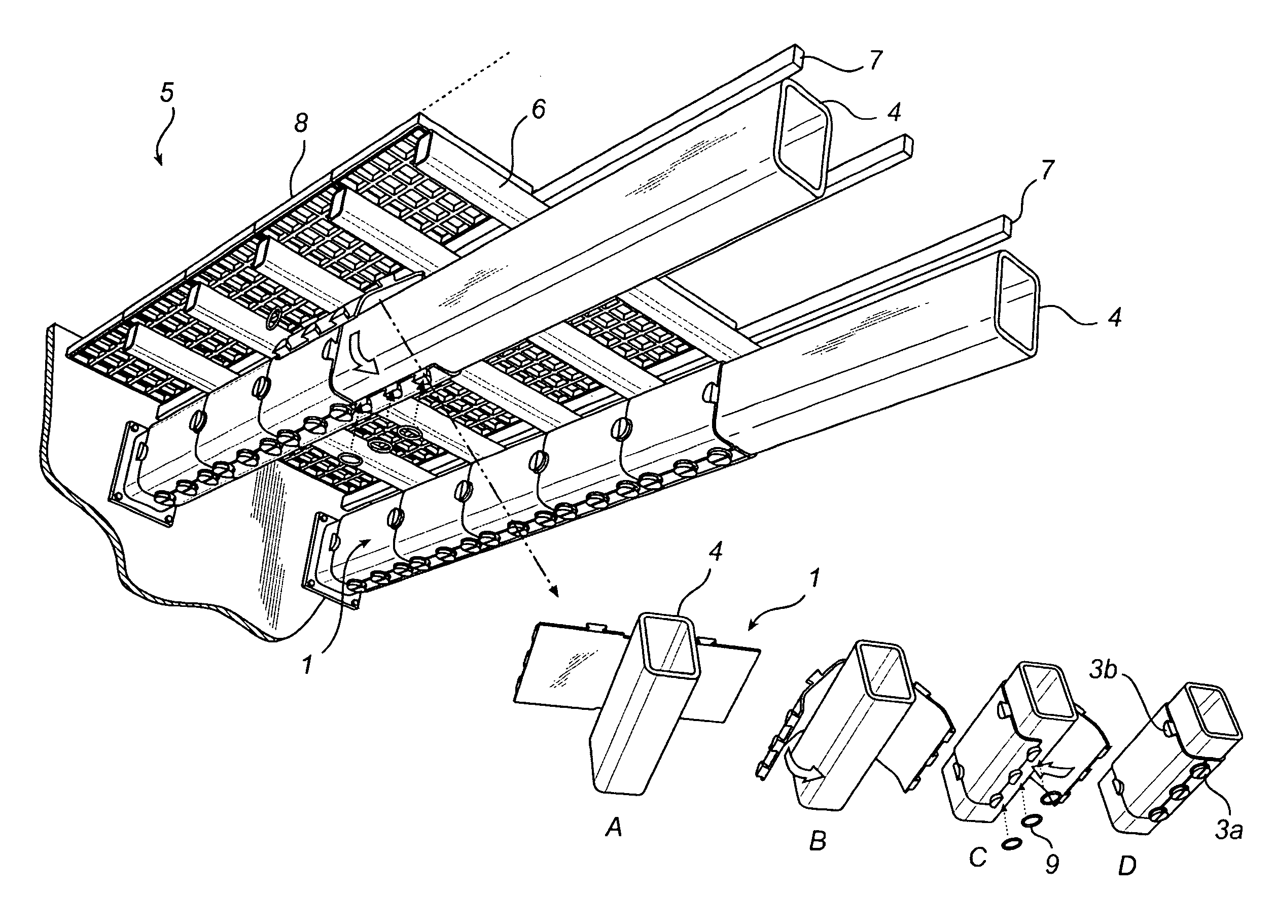
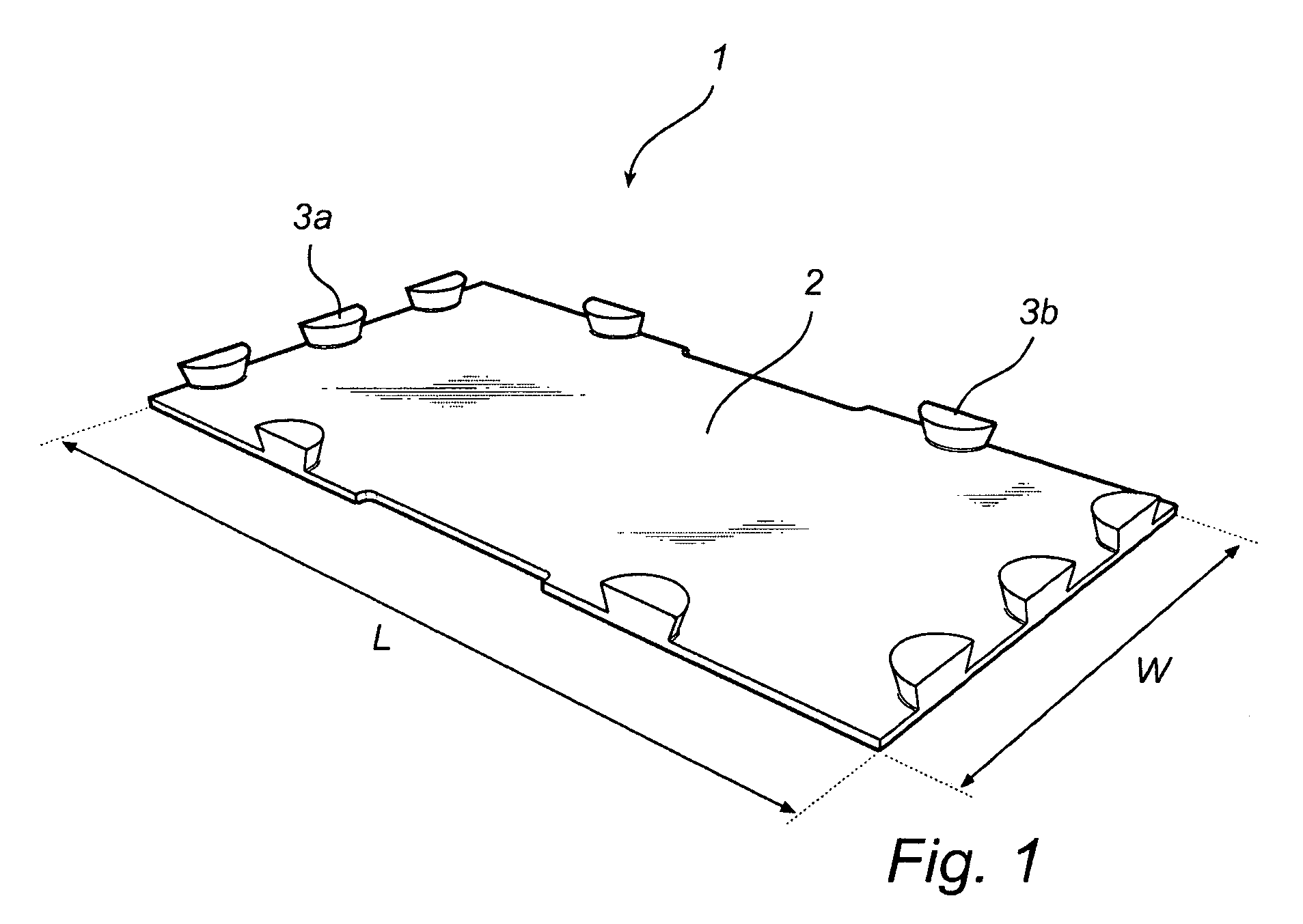
[0034]A protective element 1 is shown in FIG. 1. The protective element 1 is moulded from polyurethane, with a hardness of 60 Shore A. The body portion 2 of the protective element 1 has a thickness of 6 mm. Further, the protective element 1 is supplied with a number of projections 3a, 3b. The projections 3a, 3b are moulded from the same material and are integral with the body portion 2. The projections 3a, 3b are semicircular and have a tapered profile, meaning that the cross sectional radius of the projections 3a, 3b increases with increased distance from the body portion 2.

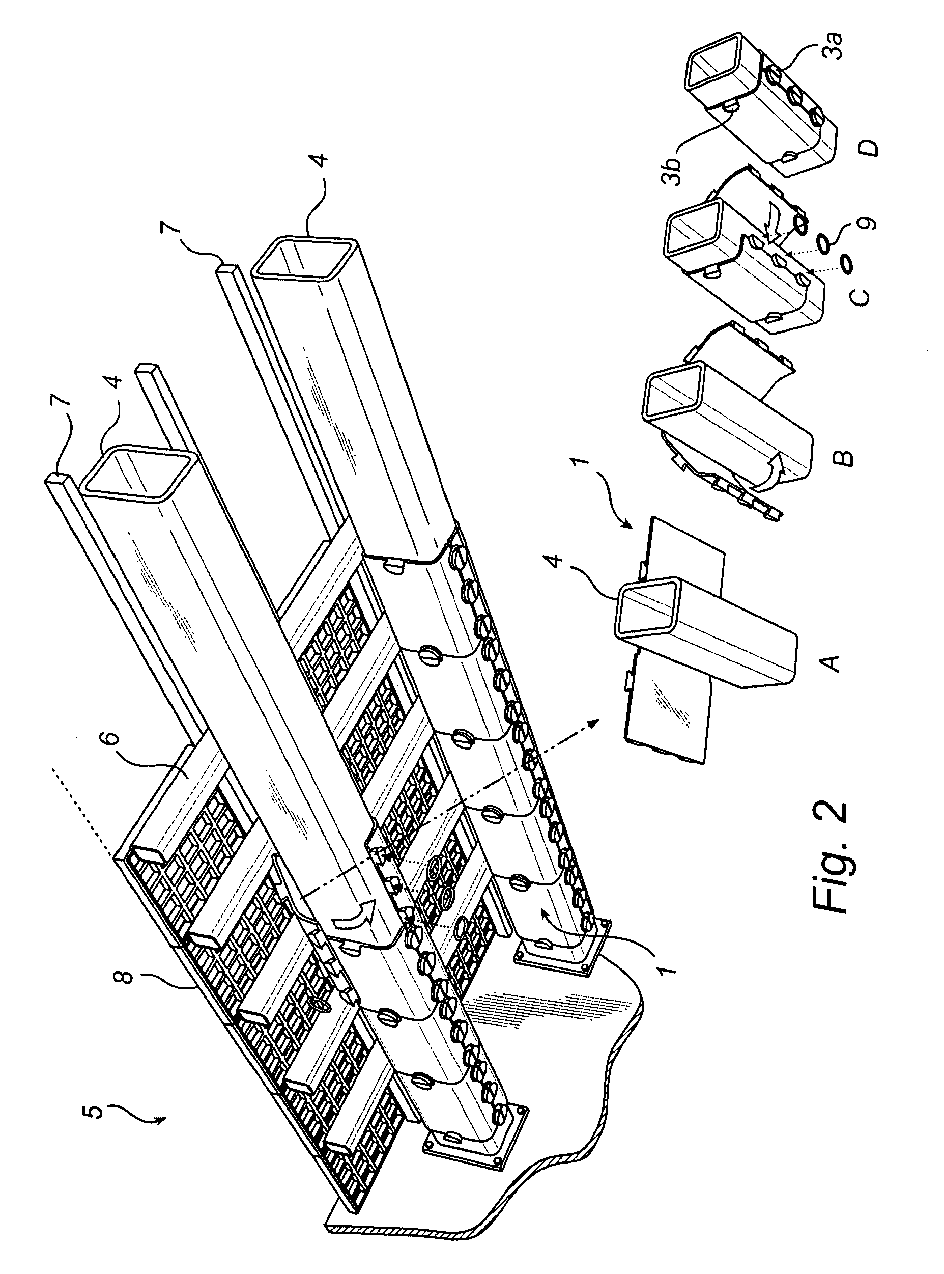
[0035]FIG. 2 illustrates schematically how a number of protective elements 1 are wrapped around two different cross members 4 of a frame in a screening arrangement 5, partially shown. The screening arrangement 5 includes a frame consisting of the lower cross members 4 and the upper cross members 6. The lower cross members 4 and the upper cross members 6 are orientated perpendicular to each other. On top of the u...


PUM


Abstract

A protective element for a cross member or shaft housing of a frame in a screening arrangement. The protective element is attachable to the cross member or shaft housing by wrapping the protective element around the cross member or shaft housing and clamping a first portion of the protective element to a second portion of the protective element by at least one clamping device. The protective element has an outwards facing surface, which is wear-resistant to withstand wear from piece goods or particle goods impinging or sliding on the outwards facing surface.

Description

FIELD OF THE INVENTION[0001]The present invention relates to a protective element for a cross member or shaft housing of a frame in a screening arrangement. The protective element is attachable to the cross member or shaft housing by wrapping the protective element around the cross member or shaft housing and clamping a first portion of the protective element to a second portion of the protective element by at least one clamping device. The protective element has an outwards facing surface, which is wear-resistant to withstand wear from piece goods or particle goods, such as crushed ore, crushed rock, sand or gravel, impinging or sliding on the outwards facing surface. The invention also relates to a protection for a cross member or shaft housing and a screening arrangement including at least one protective element.BACKGROUND ART[0002]Various screening arrangements are widely used in the industry in order to control fraction sizes of piece, particle or bulk material. In general, a s...

Claims


Application Information

Patent Timeline
Patent Type & Authority Patents(United States)
IPC IPC(8): B07B1/46
CPCB07B1/46B07B1/4618
Inventor MOORE, KEVIN
Owner METSO OUTOTEC (FINLAND) OY
Why Eureka
Try Eureka