Portable hitch mounted cargo carrier

a cargo carrier and portability technology, applied in the field of cargo carriers, can solve the problems of inability to adjust the height of the legs, difficulty in raising and lowering by hand, and the carrier has no convenient means for lifting or moving the carrier, etc., and achieves the effect of convenient transportation, easy lifting or lowering, and convenient hitching to the vehicl

Inactive Publication Date: 2011-11-22
MYREX LEE
View PDF27 Cites 26 Cited by
  • Summary
  • Abstract
  • Description
  • Claims
  • Application Information

AI Technical Summary

Benefits of technology

[0007]An advantage of the present invention is a cargo carrier that can be easily raised or lowered by screw type jacks to hitch the carrier to a vehicle.
[0008]Another advantage is a cargo carrier that has wheels which allow the carrier to be easily transported from one location to another.
[0009]Another advantage is a cargo carrier that has legs with wheels and screw type jacks, where the legs are rotatable, thereby permitting the legs to remain on the carrier when the carrier is hitched to a vehicle.
[0010]Another advantage is a cargo carrier that is easy to hitch to a vehicle by means of a U-shaped hitch sleeve which fits over a hitch shaft.
[0011]Another advantage is a cargo carrier that is simple and inexpensive to manufacture.

Problems solved by technology

These carriers have no convenient means for lifting or moving the carrier.
Although these types of cargo carriers can be transported on their wheels, they are difficult to raise and lower by hand if they are heavy.
Still other cargo carriers are known which also have rotatable legs with wheels which can be rotated up off the ground when the cargo carrier is attached to a vehicle, but the legs are not height-adjustable.
However, the jacks with wheels have to be removed from the cargo carrier after it has been hitched to a vehicle.
In addition, the jack mechanism in these jacks is exposed to the external environment which can promote fouling and / or corrosion of the jack mechanism.

Method used


Image

  • Portable hitch mounted cargo carrier
  • Portable hitch mounted cargo carrier
  • Portable hitch mounted cargo carrier

Examples


Embodiment Construction

[0024]While the following description details the preferred embodiments of the present invention, it is to be understood that invention is not limited in its application to the details of construction and arrangement of the parts illustrated in the accompanying drawings, since the invention is capable of other embodiments and of being practiced in various ways.

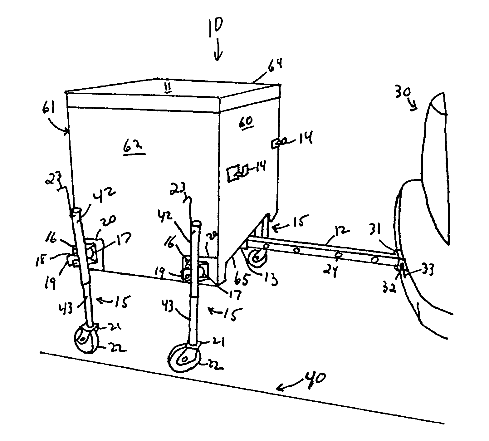
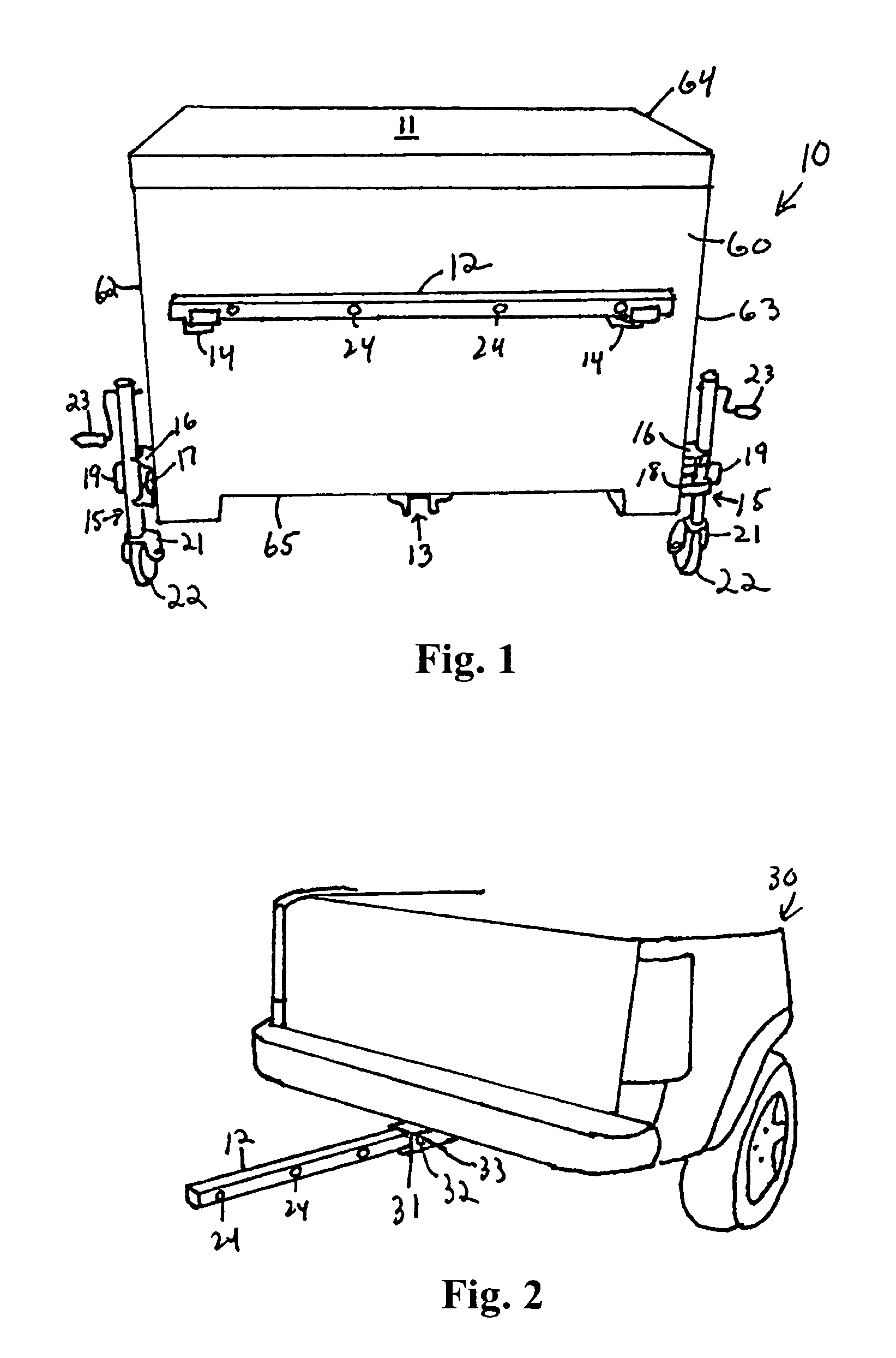
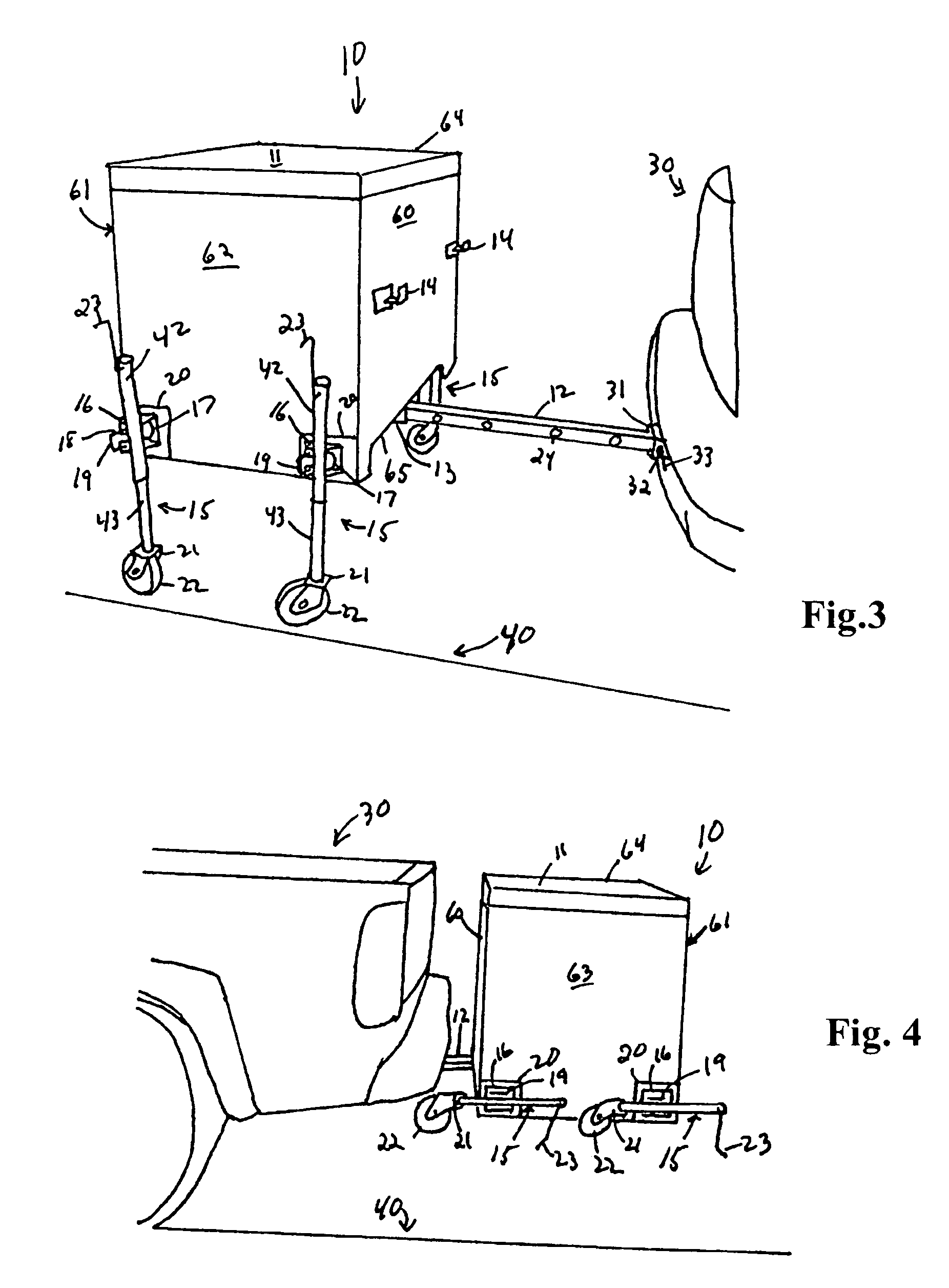
[0025]The cargo carrier 10 of the present invention is shown in FIG. 1. The cargo carrier 10 has a front 60, a back 61 (see FIG. 3), a left side 62, a right side 63, a top 64, and a bottom 65. Top 64 is constructed as a lid 11. Front 60 has a pair of hitch shaft holders 14 to hold hitch shaft 12 when cargo carrier 10 is not hitched to a vehicle. Bottom 65 has a hitch sleeve 13 centered on bottom 65. Left side 62 and right side 63 each have a pair of telescoping legs 15 and sleeves 17. Each leg has a clamp frame 16 which is fixed rotatably to sleeve 17. Clamp frame 16 has locking pins 18 (see FIG. 8) which form locking pin hand...


PUM


Abstract

A cargo carrier having a U-shaped hitch sleeve on its bottom and legs with wheels on its sides. A hitch shaft is inserted into a trailer hitch on a vehicle and the U-shaped hitch sleeve fits over the hitch shaft. The legs have an internal screw type jack mechanism to raise and lower the cargo carrier to place the U-shaped hitch sleeve above and over the hitch shaft, and to raise the legs so that the vehicle can transport the cargo carrier on the hitch shaft without having to remove the legs. The wheels allow the cargo carrier to be portable when not connected to the vehicle. They also allow the U-shaped hitch sleeve to be aligned above the hitch shaft to permit lowering the U-shaped hitch sleeve down over the hitch shaft for the insertion of bolts through the U-shaped hitch sleeve and hitch shaft, thereby fastening the cargo carrier to the hitch shaft. The legs are positioned inside the cargo carrier, and a continuous loop chain engages all the legs so that adjustment of one leg adjusts all of the legs simultaneously to raise or lower the cargo carrier.

Description

CROSS-REFERENCE TO RELATED APPLICATION[0001]This application claims the benefit of U.S. Nonprovisional patent application Ser. No. 11 / 250,898 filed Aug. 14, 2005, now abandoned, the disclosure of which is incorporated herein in its entirety as if fully set forth below.BACKGROUND OF THE INVENTION[0002]1. Field of the Invention[0003]The present invention relates to cargo carriers which can be reversibly hitched to the rear of a vehicle, and, more particularly to a cargo carrier with rotatably mounted legs with wheels that have an internal screw type jack to raise and lower the cargo carrier.[0004]2. Technical Background[0005]Cargo carriers are known which have a hitch sleeve on the bottom of the carrier and a trailer hitch shaft which can be inserted into a receiver style trailer hitch on a vehicle. The trailer hitch shaft can also be inserted into the hitch sleeve on the bottom of the carrier. These carriers have no convenient means for lifting or moving the carrier. Other cargo carr...

Claims


Application Information

Patent Timeline
Patent Type & Authority Patents(United States)
IPC IPC(8): B60R9/06
CPCB60R9/06B60R9/065
Inventor MYREX, LEE
Owner MYREX LEE
Why Eureka
Try Eureka