
Interlocking guide tracks for elliptical bike and method of use

a technology of guide tracks and elliptical bikes, applied in the field of elliptical bikes, can solve the problems of drive wheels and/or support surfaces of guide tracks that are easily damaged, drive wheels can “jump” and load wheels may uncouple from the guide tracks/frame,

Inactive Publication Date: 2011-11-22
PT MOTION WORKS INC
View PDF84 Cites 5 Cited by
  • Summary
  • Abstract
  • Description
  • Claims
  • Application Information

AI Technical Summary

Benefits of technology

The internal guide track system effectively prevents disengagement of foot links during operation, reduces wear on the frame, and allows for easy replacement of worn parts, minimizing cost and weight while maintaining efficient propulsion.

Problems solved by technology

In the past, additional coupling mechanisms have been provided to keep the load wheels on the guide tracks / frame; however, during some operations of the elliptical bicycle (e.g. when going over bumps), the load wheels may uncouple from the guide tracks / frame.
Another problem that occurs is fast wear on the drive wheels and / or support surface of the guide tracks.
If there is too much space (i.e., too much gap spacing) between the drive wheels and the top of the internal guide track system, the drive wheels can “jump” the guidance features in the lower tracks and get stuck at an angle or rub against the sides of the guide track tubes.
If the spacing is too tight, there will be too much contact / friction between the tops of the drive wheels and the top of the internal guide track system.
Getting this gap spacing correct is complicated by the fact that the drive wheels wear down over the lifetime of the elliptical bicycle and, thus, the gap between the drive wheels and the top of the internal guide track system will continue to increase over time.
Over time, friction caused by the interface of the guide tracks and or guide features and the foot link coupler will cause both the coupler and the guide tracks and / or guide features to wear.
If the guide tracks and / or guide features were not removable, then a larger structure would have to be made of the hard or hard-coated material adding cost and weight.

Method used


Image

  • Interlocking guide tracks for elliptical bike and method of use
  • Interlocking guide tracks for elliptical bike and method of use
  • Interlocking guide tracks for elliptical bike and method of use

Examples


Embodiment Construction

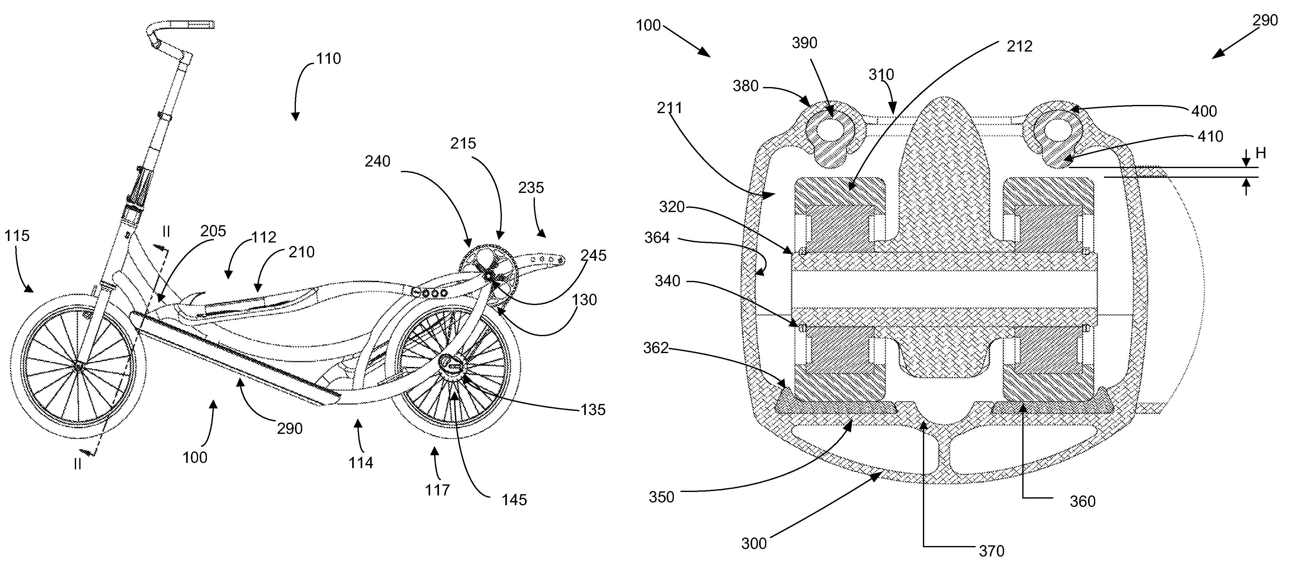
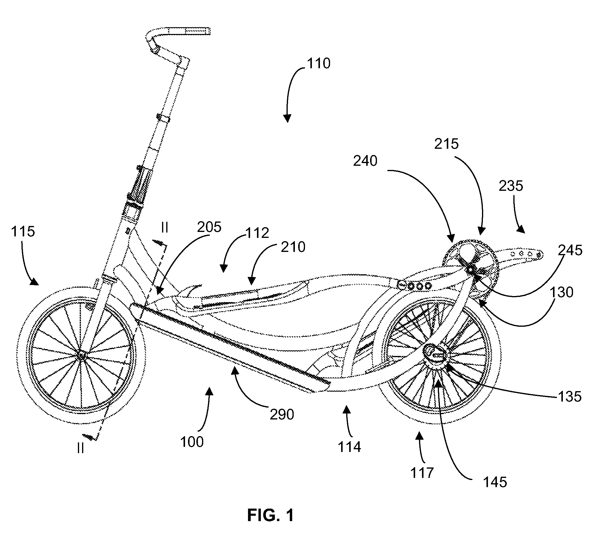
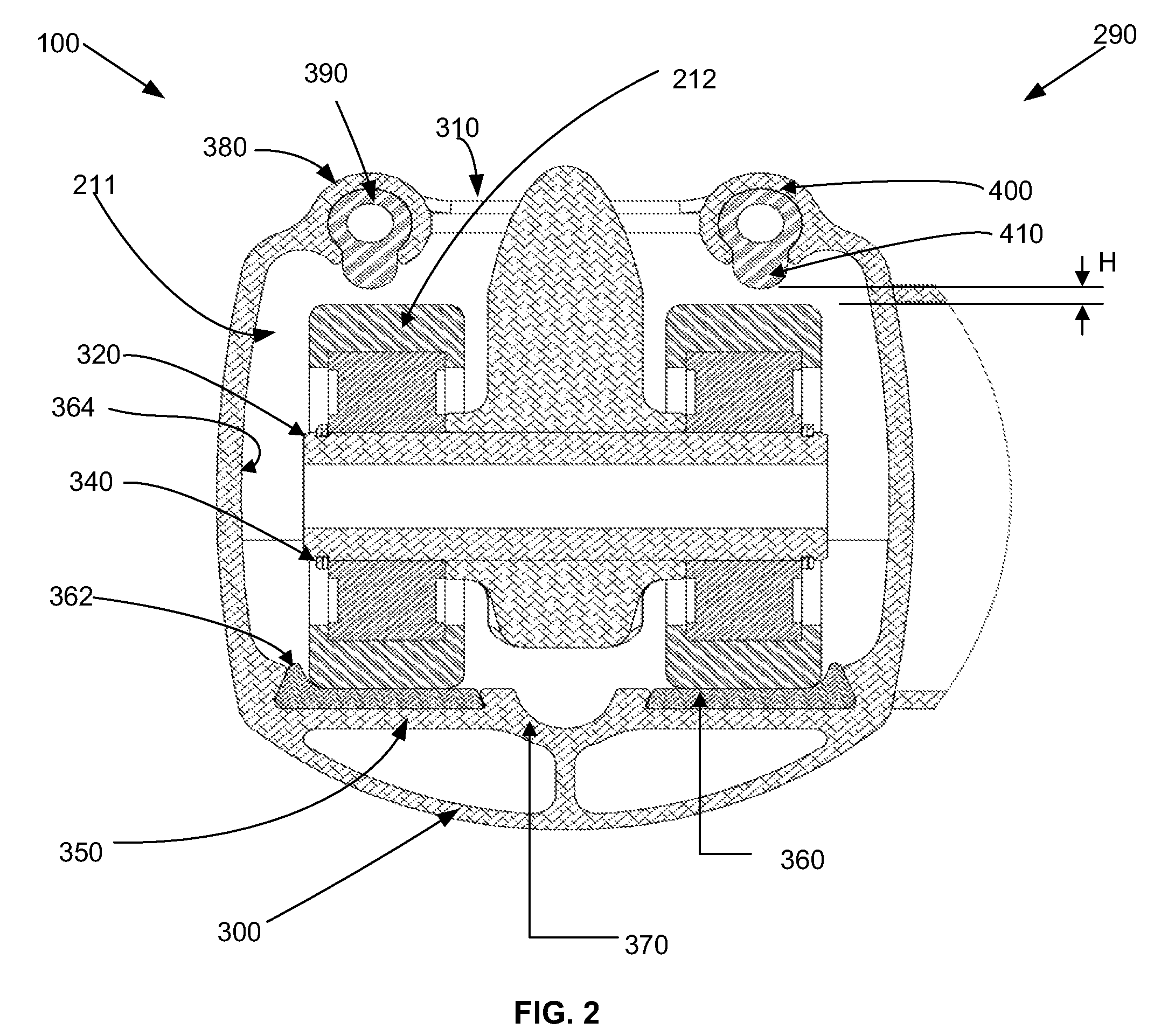
[0025]With reference to FIGS. 1 and 2, an embodiment of an internal guide track system 100 of an elliptical bicycle 110 is shown. Before describing the internal guide track system 100, the elliptical bicycle 110 will first be described.

[0026]The elliptical bicycle 110 includes a foot link assembly 112 movably mounted on a frame, or frame structure 114, on which a pair of wheels (front wheel 115, rear wheel 117) are mounted. Generally, each foot link assembly 112 is movably mounted to the frame 114 at its forward end where it is slidably coupled to a foot link guide track 290 (of the internal guide track system 100) and at its rearward end where it is rotatably coupled to a crank assembly 215.

[0027]In the present embodiment, each foot link assembly 112 includes a foot link 205, each with a foot platform 210, and a foot link coupler 211 that contacts the foot link guide track 290. In this embodiment, the foot link coupler 211 is comprised of two load wheels; however, in other embodime...


PUM


Abstract

An apparatus includes a frame with a pivot axis defined thereupon; a drive wheel coupled to the frame; a first and a second foot link operably coupled to the drive wheel to transfer power to the drive wheel so as to propel the apparatus, each including a foot receiving portion for receiving an operator's foot, a front end, and a rear end; and a pair of internal guide track systems coupled to the frame, each internal guide track system being operative to engage the front end of each foot link internal to the internal guide track system and to direct the front end along a reciprocating path of travel while providing retention to each foot link.

Description

CROSS-REFERENCE TO RELATED APPLICATIONS[0001]This application claims priority to U.S. provisional patent application 61 / 179,644 filed on May 19, 2009 and U.S. provisional patent application 61 / 179,647 filed on May 19, 2009 under 35 U.S.C. 119(e). U.S. provisional patent application 61 / 179,644 and U.S. provisional patent application 61 / 179,647 are hereby incorporated by reference as though set forth in full.BACKGROUND[0002]1. Field of the Invention[0003]The present invention relates generally to elliptical bikes, and particularly to guide tracks and features for elliptical bikes.[0004]2. Related Art[0005]U.S. Published Application 2008 / 0116655, which is incorporated by reference herein, discloses a self-propelled vehicle propelled by an elliptical drive train (hereinafter referred to as “elliptical bicycle”). In an elliptical bicycle, a user's feet are placed in foot platforms and the user strides forward and rearward, which though a variety of mechanical mechanisms, causes a rear wh...

Claims


Application Information

Patent Timeline
Patent Type & Authority Patents(United States)
IPC IPC(8): B62M1/36B62M1/24
CPCB62K3/002B62K2015/003B62M1/26B62M3/02
Inventor TEAL, BRENT C.PATE, BRYAN L.
Owner PT MOTION WORKS INC
Learn More