Eureka AIR delivers breakthrough ideas for toughest innovation challenges, trusted by R&D personnel around the world.

Ink jet recording head

a recording head and liquid ejection technology, applied in the direction of printing, inking apparatus, etc., can solve the problems of prolonged ink re-supply time, shortened printing speed, and increased production costs, so as to prevent the lengthening of ink re-supply time and reduce the degree of cross-talk

Inactive Publication Date: 2011-11-22
CANON KK
View PDF20 Cites 3 Cited by
  • Summary
  • Abstract
  • Description
  • Claims
  • Application Information

AI Technical Summary

Benefits of technology

[0016]The present invention can solve the above-described problems. A principal object of the present invention is to provide an ink jet recording head which has prevented lengthening in ink re-supplying time with respect to nozzles and has reduced a degree of cross-talk between adjacent nozzles.
[0024]In the present invention, by employing such a structure that a flow resistance is different depending on a flowing direction of ink through a flow passage for connecting adjacent nozzles, it is possible to prevent the lengthening in ink re-supplying time and reduce the degree of the cross-talk.

Problems solved by technology

However, when the degree of the cross-talk is intended to be reduced by the above-described means, such a problem that it takes time to re-supply the ink has arisen.
When the re-supply of the ink requires time, a drivable frequency cannot be set at a higher level, with the result that a printing speed is lowered.
In this method, however, a flow resistance of the liquid flow passage 7 of each nozzle is increased, so that there arises a problem such that an ink re-supplying time is prolonged.

Method used


Image

  • Ink jet recording head
  • Ink jet recording head
  • Ink jet recording head

Examples


embodiment 1

[0032]A constitution of a recording head of this embodiment will be described with reference to the drawings.

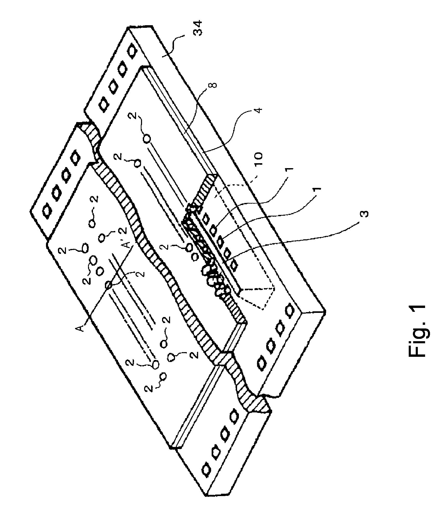
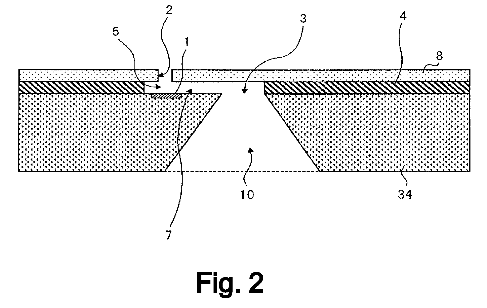
[0033]FIG. 1 is a perspective view of the recording head of this embodiment and FIG. 2 is a sectional view of the recording head taken along a line segment A-A′ shown in FIG. 1. Not only in FIGS. 1 and 2 but also in other figures, a constitution of electrical wiring and the like for driving electrothermal transducer elements 1 is the same as in a conventional recording head, so that constituent members or portions thereof will be omitted from illustration and detailed description.

[0034]As shown in FIG. 1, on a substrate 34, an ejection outlet plate 8 is provided. An ink supplying chamber 10 is connected to a common liquid chamber and a liquid flow passage of an ejection portion through an ink supply port 3 of an opening portion provided on the substrate surface.

[0035]As shown in FIG. 1, on a surface of the substrate 34, the electrothermal transducer elements 1 as elements for...

embodiment 2

[0049]In this embodiment, the adjacent nozzles are different in ink ejection amount.

[0050]FIG. 4 is a front view of an ejection portion of a recording head of this embodiment. In this embodiment, the ejection outlet plate 8 and the flow passage constituting portion 4 are formed of the same member but can achieve a similar effect even when they are provided as different members.

[0051]As shown in FIG. 4, in this embodiment, a resistance member 13 is provided in a common liquid chamber 260 between the flow passage constituting portion 4 and the ink supply port 3.

[0052]Nozzles 200 having a predetermined ink ejection amount for one ejection (shot) and nozzles 210 having an ink ejection amount larger than the predetermined ink ejection amount are alternately disposed. An electrothermal transducer element 15 of the nozzle 200 is smaller in size than an electrothermal transducer element 16 of the nozzle 210, thus being smaller in amount of the ink flowing toward the liquid flow passage side...


PUM


Abstract

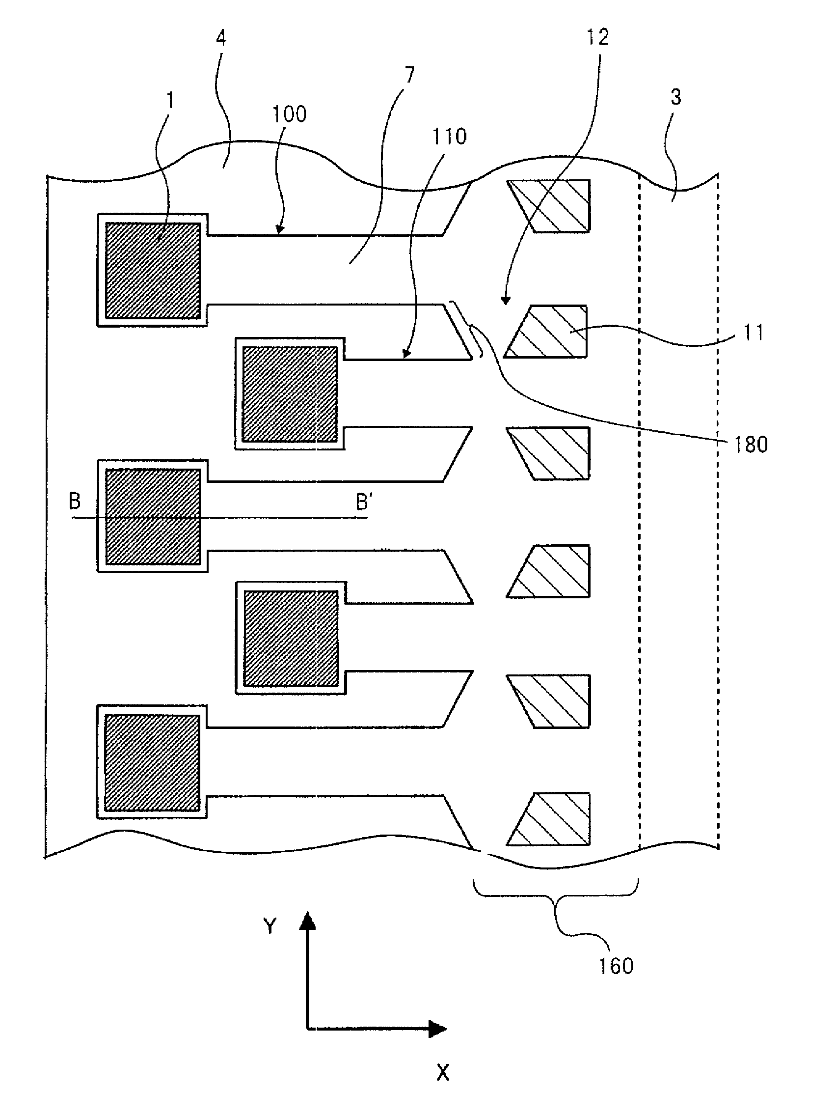
An ink jet recording head includes ejection energy generating elements for ejecting ink, flow passages for supplying the ink from an ink supply port to the ejection energy generating elements through a common liquid chamber, a partition wall formed between adjacent two flow passages, a member disposed between the partition wall and the ink supply port, and an opening formed between the partition wall and the member. A flow resistance in the opening from one of the adjacent two flow passages to the other flow passage is different from that in the opening from the other flow passage to the one of the adjacent two flow passages.

Description

FIELD OF THE INVENTION AND RELATED ART[0001]The present invention relates to a recording apparatus and a liquid ejection recording head, particularly an ink jet recording head.[0002]As one of ink jet recording apparatuses, a bubble jet (registered trademark) recording apparatus has been known. In this recording apparatus, energy such as heat or the like is imparted to ink, so that the ink is caused to bring about a change in state with abrupt volume change (bubble generation) and is ejected from an ejection outlet by an acting force on the basis of this change in state, thereby to be deposited on a recording medium (material) to carry out image formation.[0003]An ink jet recording head used in such an ink jet recording apparatus will be briefly described. The recording head generally includes an ejection portion provided with ejection outlets for ejecting the ink, liquid flow passages for introducing the ink into these ejection outlets, and ejection heaters. The ejection heater is a...

Claims


Application Information

Patent Timeline
Patent Type & Authority Patents(United States)
IPC IPC(8): B41J2/05B41J2/04
CPCB41J2/1404B41J2002/14387B41J2002/14403B41J2202/11
Inventor MURAKAMI, SHUICHI
Owner CANON KK
Why Eureka
Eureka Blog
Learn More