
Image noise measurement system and method

a noise measurement and image technology, applied in the field of image processing, can solve the problems of noise reduction in either spatial or temporal domain, possible problems such as noise, and the likelihood of interference in transmission of tv signals to have noises, so as to avoid the measured noise level, reliable noise estimate, and eliminate noise estimates

Inactive Publication Date: 2011-11-22
SUNPLUS TECH CO LTD
View PDF10 Cites 8 Cited by
  • Summary
  • Abstract
  • Description
  • Claims
  • Application Information

AI Technical Summary

Benefits of technology

[0011]An object of the present invention is to provide an image noise measurement system and method, which eliminates the noise estimates with great differences and avoids the measured noise level being affected by a motion interference, thereby obtaining a reliable noise estimate.
[0012]Another object of the present invention is to provide an image noise measurement system and method, which can find the noise level in a time interval without setting the threshold.

Problems solved by technology

Generally, TV signals are likely to suffer from the interference in transmission to thus have noises.
However, the noise reduction in either spatial or temporal domain possibly produces various problems.
However, the method for spatial noise reduction cannot completely separate the noises from the video components in space, and thus the side effect of blurs easily present in the video.
Generally, a viewer shows high tolerance in the side-effects caused by the noise reduction when the noise is at a high level, but the viewer shows relatively low tolerance in the side-effects when the noise is at a low level.
However, a picture contains the different proportions of motion areas, and accordingly the expected value cannot be predetermined easily and the noise level measurement can be easily affected by the number of pixels corresponding to the motion areas in the frame.
However, a typical TV display system does not contain a motion estimation and compensation operation.
Accordingly, the distribution of the temporal local difference is gradually changed with the different motions, which increases the difficulty of finally determining to remain or discard the threshold.

Method used


Image

  • Image noise measurement system and method
  • Image noise measurement system and method
  • Image noise measurement system and method

Examples


Embodiment Construction

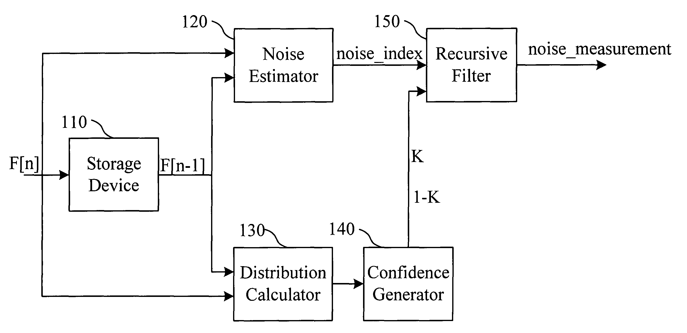
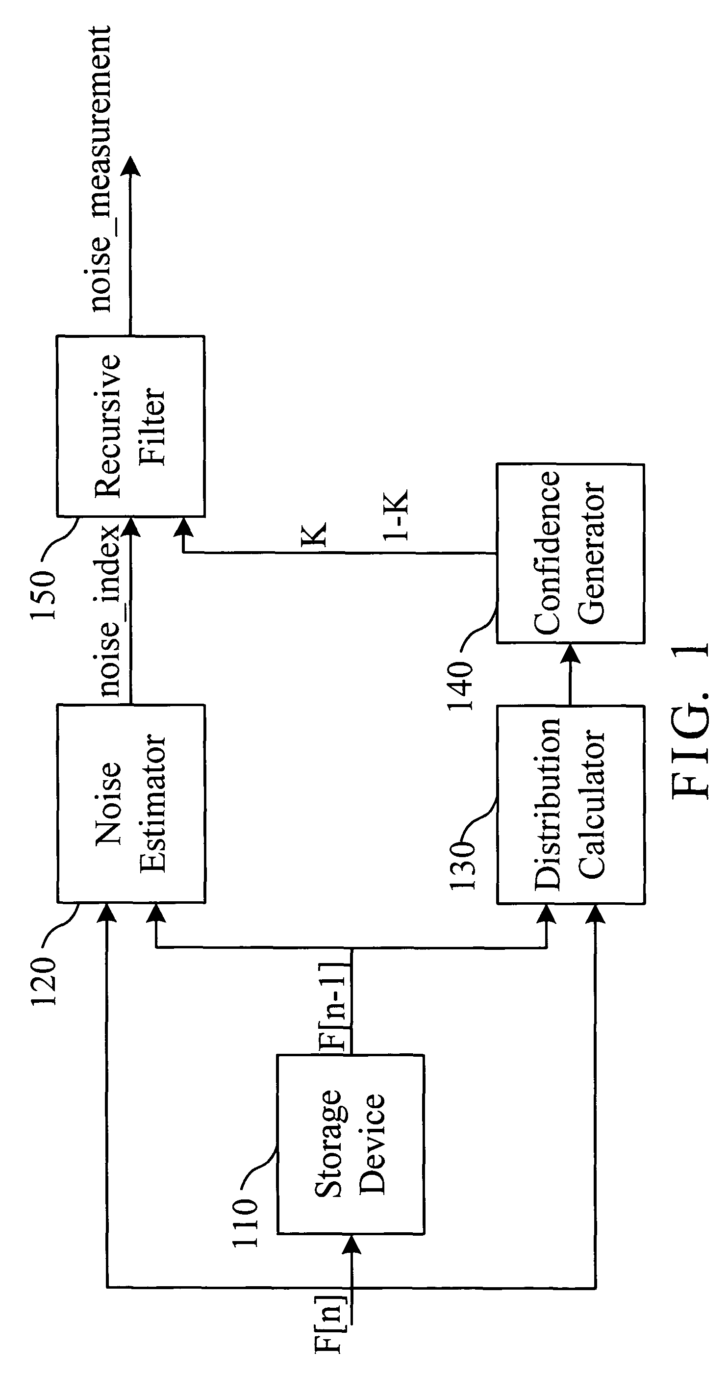
[0020]FIG. 1 is a block diagram of an image noise measurement system according to the invention. The system performs a noise estimation on an image F[n] to thereby produce a noise estimate for the image F[n]. The system includes a storage device 110, a noise estimator 120, a distribution calculator 130, a confidence generator 140 and a recursive filter 150.

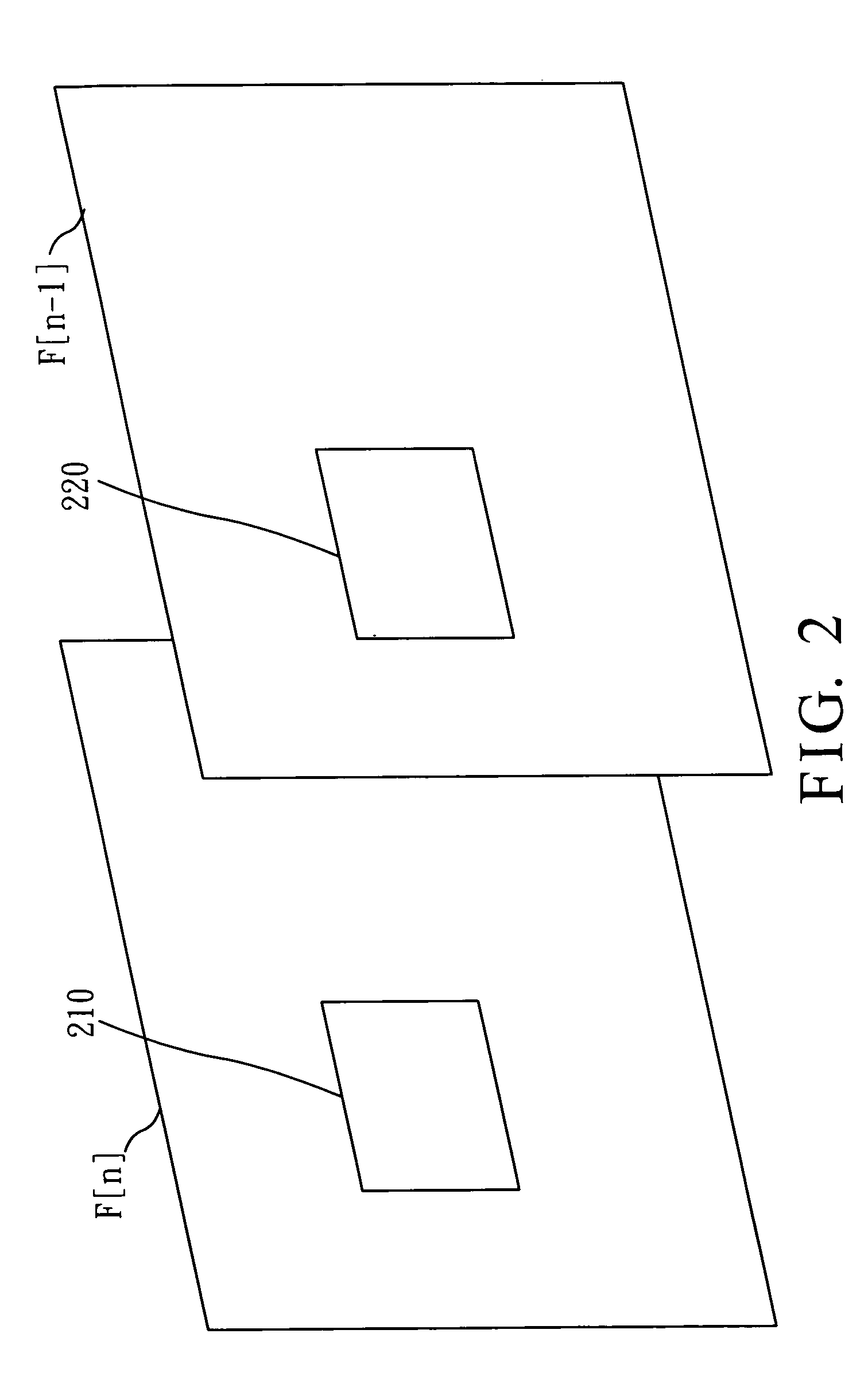
[0021]The storage device 110 stores a previous image F[n−1]. The noise estimator 120 is connected to the storage device 110 in order to perform a noise estimation on sub-areas of the image F[n] and the previous image F[n−1] and to produce a noise estimation index noise_index corresponding to the sub-area of the image F[n].

[0022]The distribution calculator 130 is connected to the noise estimator 120 in order to calculate a distribution of positive and negative signs of pixel differences in the sub-areas of the image F[n] and the previous image F[n−1] that are covered by the noise estimator and to output a positive sign number No(+)...


PUM


Abstract

An image noise measurement system performs a noise estimation on a current image. A storage device stores a previous image. A noise estimator performs a noise estimation on sub-areas of the current image and the previous image to thereby produce a noise estimation index for the sub-area of the current image. A distribution calculator calculates a distribution of positive and negative signs of pixel differences in the sub-areas of the current image and the previous image to thereby output a positive sign number and a negative sign number. A confidence generator produces a confident level index according to the positive sign number and the negative sign number. A recursive filter performs a recursive filtering operation on the noise estimation index according to the confident level index to thereby produce a noise estimate for the current image.

Description

BACKGROUND OF THE INVENTION[0001]1. Field of the Invention[0002]The present invention relates to a method of image processing and, more particularly, to a system of an image noise measurement and the method thereof.[0003]2. Description of Related Art[0004]Generally, TV signals are likely to suffer from the interference in transmission to thus have noises. To reduce the interference of the noises, a noise reduction is typically provided in a display section. However, the noise reduction in either spatial or temporal domain possibly produces various problems. Typically, the noise reduction is performed by first analyzing the noise levels of input images and then taking various noise reduction processes according to the noise levels analyzed.[0005]U.S. Pat. No. 5,844,627 granted to May, et al. for a “Structure and method for reducing spatial noise” describes a method for spatial noise reduction, which first analyzes the spatial frequency components and then suppresses the possible band...

Claims


Application Information

Patent Timeline
Patent Type & Authority Patents(United States)
IPC IPC(8): H04N5/00H04N5/14G06K9/40
CPCH04N5/21
Inventor PENG, YUAN-CHIH
Owner SUNPLUS TECH CO LTD
Learn More