Liquid crystal display panel having an ornamental reflector deployed around the periphery of a display region

a technology of ornamental reflectors and display regions, applied in non-linear optics, instruments, optics, etc., can solve problems such as difficulty in adopting such a structure immediately, and achieve the effect of fine white appearance and good ornamental

Inactive Publication Date: 2011-11-22
JAPAN DISPLAY WEST
View PDF12 Cites 3 Cited by
  • Summary
  • Abstract
  • Description
  • Claims
  • Application Information

AI Technical Summary

Benefits of technology

As a result of various investigations aimed at resolving the night vision phenomenon alongside the scan line wiring 171 of the border region 34 due to the foregoing causes, the inventors have found that the phenomenon of the border region 34 appearing dark along the scan line wiring 171 as described above is not generated, when there is no potential difference between the opposed electrode 31 and the transparent electrode 38. However, it was difficult to adopt such a structure immediately, because of increase in manufacturing steps and manufacturing cost. By conducting further research, the inventors have found that when at least an outer peripheral side, or more preferably, all of the opposed electrode 31 at a position corresponding to the border region 34 does not exist, a state that the electric field is not applied to the liquid crystal molecules can be created. This enables to eliminate the phenomenon that the border region 34 appears dark along the scan line wirings 171, thereby completing the present invention.
According to the above liquid crystal display panel of the invention, at least a part of the outer peripheral side is not being provided to the common electrode at the position corresponding to the ornamental reflective part. As there is no electric field applied to the liquid crystal layer by a signal voltage being applied to the scan line wiring, it does not appear dark with lines along the scan line wiring as in the related art. As a result, the liquid crystal display panel having the ornamental reflective part, that is, the border region, with an attractive appearance in white which uses reflection of external light by the reflector can be obtained. In such a case, by not providing all the common electrodes at the position corresponding to the ornamental reflective part, the electric field applied to the liquid crystal layer by the signal voltage being applied to the scan line wiring can be eliminated substantially and completely. But taking into account the likelihood of influence from electrostatic charges from outside, and to prevent the common electrode corresponding to the display region from misplacing by a mask misalignment during manufacturing, it is preferable not to provide at least a part of the outer peripheral side of the common electrode at the position corresponding to the ornamental reflective part.
According to the above liquid crystal display panel, there is no need to adopt a special manufacturing method or a manufacturing step anew, so that the common electrode at the position corresponding to the ornamental reflective part does not provide a part of the outer peripheral side. As a result, the liquid crystal display panel having the border region which produces a good ornamental effect can be obtained with ease without increasing manufacturing steps.
According to the above liquid crystal display panel, the pixel electrode is formed in the display region. As the pixel electrode is formed by the transparent electrode, the structure of the ornamental reflective part can be made approximately the same as the structure of the display region, when the transparent electrode is also formed to the ornamental reflective part. As a result, a difference in appearance between the display region and the ornamental reflective part is reduced, and the liquid crystal display panel having the border region which produces a good ornamental effect can further be obtained.
According to the above liquid crystal display panel, light entered from outside becomes diffused reflected light, as the reflector of the ornamental reflective part has the concavoconvex structure. As a result, it looks pure white, and the liquid crystal display panel which produces a good ornamental effect can be obtained.
Also, in the above liquid crystal display panel, it is possible, not only for the transmissive type of liquid crystal display panel but also for the semi-transmissive or the reflective type, to obtain a liquid crystal display panel that yields an ornamental effect with a fine white appearance.

Problems solved by technology

However, it was difficult to adopt such a structure immediately, because of increase in manufacturing steps and manufacturing cost.

Method used


Image

  • Liquid crystal display panel having an ornamental reflector deployed around the periphery of a display region
  • Liquid crystal display panel having an ornamental reflector deployed around the periphery of a display region
  • Liquid crystal display panel having an ornamental reflector deployed around the periphery of a display region

Examples


first embodiment

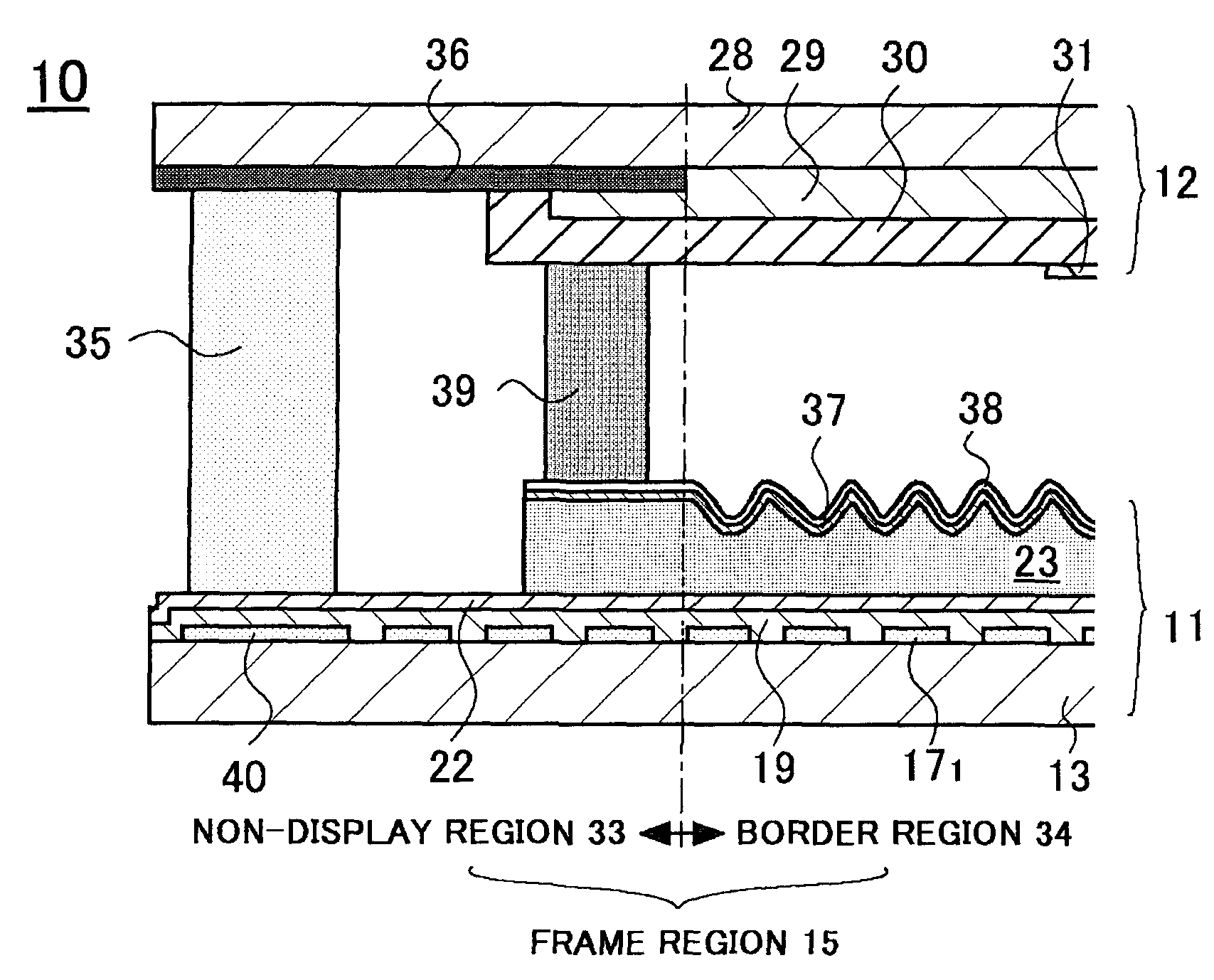
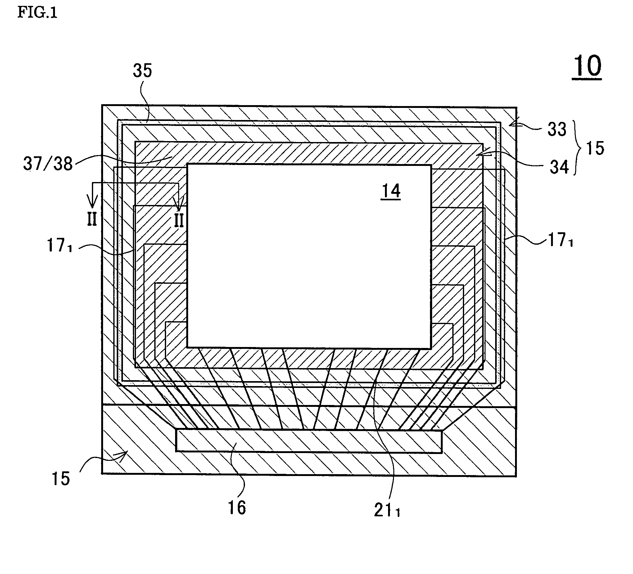
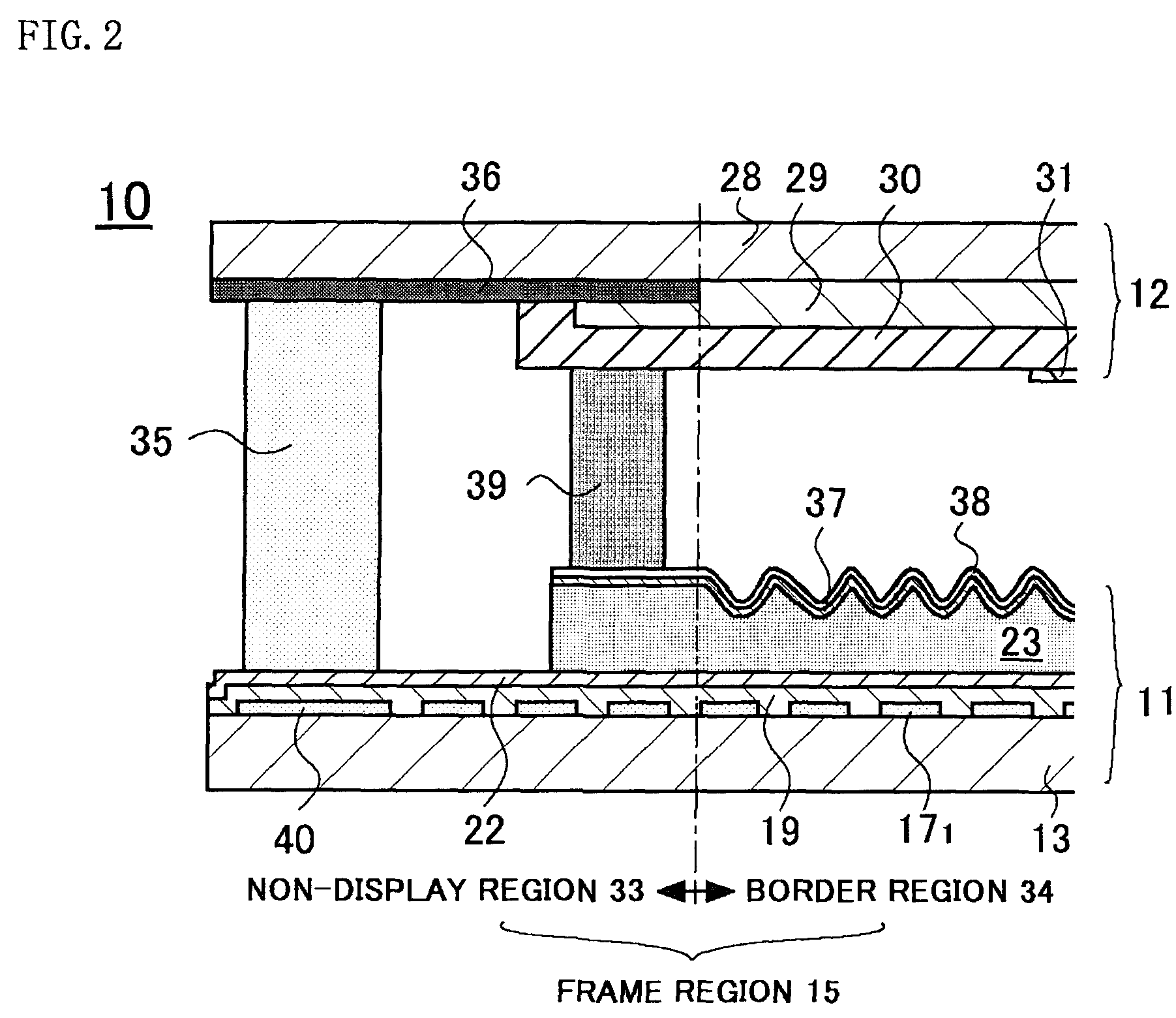
A semi-transmissive liquid crystal display panel 10 of a first embodiment is described below using FIGS. 1 to 2. FIG. 1 is a schematic plan view of a single-terminal type semi-transmissive liquid crystal display panel according to the first embodiment. FIG. 2 is a cross-sectional view along line II-II in FIG. 1. Since the configuration of the pixels in the display region of the array substrate in the semi-transmissive liquid crystal display panel 10 of the first embodiment is substantially the same as that of the related art items shown in FIGS. 5 and 6, component elements that are identical to those in the related art cases are assigned the identical reference numerals, and where necessary are described with the aid of FIGS. 5 and 6.

The semi-transmissive liquid crystal display panel 10 of the first embodiment has an array substrate 11 and a opposed substrate 12 that are opposed to each other and hold a liquid crystal layer between them. The array substrate 11 has a transparent subs...


PUM

PropertyMeasurementUnit
thickness L1aaaaaaaaaa
voltageaaaaaaaaaa
voltageaaaaaaaaaa

Abstract

A liquid crystal display panel 10 of the present invention includes an array substrate 11 with a display region in which a pixel electrode is formed in each of the regions enclosed by a plurality of signal lines and scan lines deployed as matrices, a opposed substrate 12 with a common electrode 31, a sealing agent 35 sealing a peripheral portion of the array substrate 11 and the opposed substrate 12, a liquid crystal layer sealed between both substrates, a border region 34 including a reflector 37 and a transparent electrode 38 is formed on an interlayer 23 at a periphery of the display region of the array substrate 11, and at least a part of an outer peripheral side is lacking from the common electrode 31 at a position corresponding to the border region 34. Thanks to such structure, the border region improves the appearance at the periphery of the display region, and the phenomenon of night vision alongside the scan line wiring does not occur.

Description

BACKGROUND1. Technical FieldThe present invention relates to a liquid crystal display panel. More particularly the present invention relates to a liquid crystal display panel having an ornamental reflective part (border region) for improving the appearance around the periphery of the display region, wherein dark lines do not appear alongside the scan line wiring in the border region.2. Related ArtOver recent years the application of liquid crystal display panels has spread rapidly, not only in information and telecommunications equipment but in electrical equipment in general. Since liquid crystal display panels do not themselves emit light, the transmissive type of liquid crystal display panel that is equipped with a backlight is much employed.However, since backlights consume large amounts of power, the reflective type of liquid crystal display panel which does not need a backlight have been used, especially for portable equipment, in order to reduce power consumption. But reflect...

Claims


Application Information

Patent Timeline
Patent Type & Authority Patents(United States)
IPC IPC(8): G02F1/1335G02F1/1333
CPCG02F1/1339G02F1/1345G02F2001/133388G02F2203/02G02F1/133388
Inventor NAKAHARA, TAETANAKA, SHINICHIROKANEKO, HIDEKITANIGUCHI, HIRONORIARIGA, MASASHI
Owner JAPAN DISPLAY WEST
Why Eureka
Try Eureka