Head stack assembly with flexure tail retention features

a technology of head stack and tail, which is applied in the direction of maintaining head carrier alignment, recording information storage, instruments, etc., can solve the problems of flexure tail excessive flutter, read/write errors, debris particles that can undesirably contaminate the head/disk interface,

Active Publication Date: 2011-11-22
WESTERN DIGITAL TECH INC
View PDF19 Cites 59 Cited by
  • Summary
  • Abstract
  • Description
  • Claims
  • Application Information

AI Technical Summary

Benefits of technology

[0009]A novel head stack assembly (HSA), and method for HSA assembly, are disclosed and claimed. An actuator includes an actuator body and an actuator arm extending from the actuator body. A flex cable is attached to the actuator. A first head gimbal assembly (HGA) is attached to the actuator arm. The first HGA includes a load beam, a first laminated flexure attached to the load beam, and a head attached to the first laminated flexure. The first laminated flexure includes a first flexure tail attached to the flex cable. The first flexure tail has a long axis approximately parallel to a side of the actuator arm. The actuator arm includes a slot in the side having a slot end. The first flexure tail is disposed partially within the slot. The first flexure tail includes a first raised region in contact with the slot adjacent the slot end. The first raised region includes an out-of-plane bend with cross-sectional curvature along the long axis. The first raised region may be squeezed while inserting the first flexure tail partially within the side slot, with the first raised region adjacent the slot end, and then allowed to expand into contact with the slot adjacent the slot end.

Problems solved by technology

If the flexure tail is not adequately secured to the actuator arm, air induced by disk rotation can cause the flexure tail to excessively flutter.
Excessive flutter is undesirable because it can lead to excessive vibration of adjacent components, causing dynamic disturbances that can induce read / write errors.
Excessive flutter may also cause contact locations between the flexure tail and actuator arm to wear, thereby generating debris particles that can undesirably contaminate the head / disk interface.
On the other hand, adhesive tacking is undesirable because it is both a risky and cumbersome manufacturing process in a high-volume manufacturing environment.
Disk drive components are typically assembled in clean rooms because small amounts of contamination can result in manufacturing yield loss due to interference with the operation of sensitive and high-precision components such as magnetic recording heads.
Control of the spread of adhesive and its constitutive chemicals represents a formidable challenge in high volume disk drive manufacture, and therefore processes that require adhesive are not favored.

Method used


Image

  • Head stack assembly with flexure tail retention features
  • Head stack assembly with flexure tail retention features
  • Head stack assembly with flexure tail retention features

Examples


Embodiment Construction

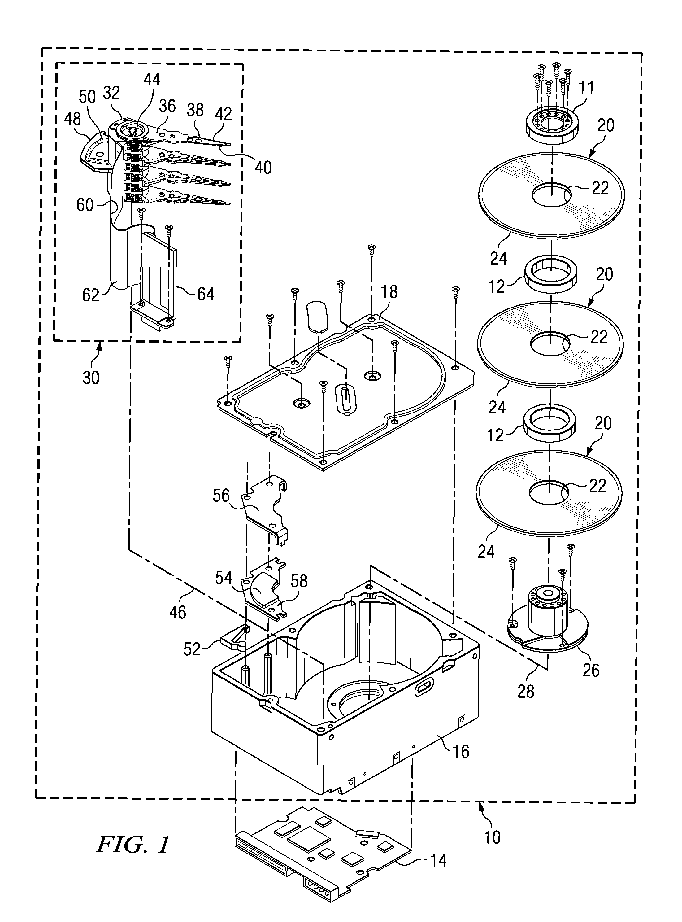
[0025]FIG. 1 illustrates a disk drive according to an embodiment of the present invention. The disk drive includes a head disk assembly (HDA) 10 and a printed circuit board assembly (PCBA) 14. The base 16 and cover 18 of HDA 10 house at least one annular magnetic disk 20. Each disk 20 contains a plurality of magnetic tracks for storing data. The tracks are disposed upon opposing first and second disk surfaces of the disk 20 that extend between an inner disk edge 22 (corresponding to the inner diameter) and an outer disk edge 24 (corresponding to the outer diameter) of the disk 20. The head disk assembly 10 further includes a spindle motor 26 for rotating the disk 20 about a disk axis of rotation 28. The spindle motor 26 includes a spindle motor hub that is rotatably attached to the base 16 of the HDA 10. Disks 20 may be stacked and separated with one or more annular disk spacers 12 that are disposed about the hub, all fixed to the hub by disk clamp 11.

[0026]The HDA 10 further includ...


PUM

PropertyMeasurementUnit
thicknessaaaaaaaaaa
conductiveaaaaaaaaaa
electrical connectionaaaaaaaaaa

Abstract

A novel head stack assembly (HSA), and method for HSA assembly, are disclosed and claimed. A first flexure tail has a long axis approximately parallel to a side of the actuator arm. The actuator arm includes a slot in the side having a slot end. The first flexure tail is disposed partially within the slot. The first flexure tail includes a first raised region in contact with the slot adjacent the slot end. The first raised region includes an out-of-plane bend with cross-sectional curvature along the long axis. The first raised region may be squeezed while inserting the first flexure tail partially within the side slot, with the first raised region adjacent the slot end, and then allowed to expand into contact with the slot adjacent the slot end.

Description

BACKGROUND OF THE INVENTION[0001]1. Field of the Invention[0002]The present invention relates generally to the field of information storage devices, and more particularly to head stack assemblies used in such devices.[0003]2. Background of the Art[0004]Information storage devices are used to retrieve and / or store data in computers and other consumer electronics devices. A magnetic hard disk drive is an example of an information storage device that includes one or more heads that can both read and write, but other information storage devices also include heads—sometimes including heads that cannot write.[0005]In a modern magnetic hard disk drive device, each head is a sub-component of a head-gimbal assembly (HGA) that typically includes a laminated flexure to carry the electrical signals to and from the head. The HGA, in turn, is a sub-component of a head-stack assembly (HSA) that typically includes a plurality of HGAs, an actuator, and a flex cable. The plurality of HGAs is attached...

Claims


Application Information

Patent Timeline
Patent Type & Authority Patents(United States)
IPC IPC(8): G11B5/58
CPCG11B5/4833G11B5/486Y10T29/49025Y10T29/4903Y10T29/49032Y10T29/49027
Inventor ZHANG, YIDUOPAN, TZONG-SHIICHEN, YIH-JEN D.
Owner WESTERN DIGITAL TECH INC
Why Eureka
Try Eureka