LED lighting tube with rotational end caps

Inactive Publication Date: 2011-11-29
RELED SYST
View PDF20 Cites 19 Cited by
  • Summary
  • Abstract
  • Description
  • Claims
  • Application Information

AI Technical Summary

Benefits of technology

[0007]The rotatable electrical coupling has a limiter insert that provides a rotative stop, a collet that at least partially surrounds the limiter insert and is rotatable about the limiter insert, and an interface connector secured to the limiter insert and in electrical communication with the circuit board. The rotatable electrical coupling permits the LED lighting tube to connect to a light fixture while also permitting the cylindrical housing to rotate relative to the light fixture. The rotation of the collet about the limiter insert is limited by the rotative stop.
[0008]In embodiments having three or more segments, there is a rotating connector between each internal segment, which does not have a rotatable electrical coupling since the internal segment need not connect to a light fixture. In such versions, the device can be configured so that each LED can rotate relative to the other LED.

Problems solved by technology

The segments of the lamp are also able to rotate for precise aiming of the LED, and this rotation is limited to prevent over-rotation and associated problems.

Method used


Image

  • LED lighting tube with rotational end caps
  • LED lighting tube with rotational end caps
  • LED lighting tube with rotational end caps

Examples


Embodiment Construction

[0022]The detailed description set forth below in connection with the appended drawings is intended as a description of presently-preferred embodiments of the invention and is not intended to represent the only forms in which the present invention may be constructed or utilized. The description sets forth the functions and the sequence of steps for constructing and operating the invention in connection with the illustrated embodiments. However, it is to be understood that the same or equivalent functions and sequences may be accomplished by different embodiments that are also intended to be encompassed within the spirit and scope of the invention.

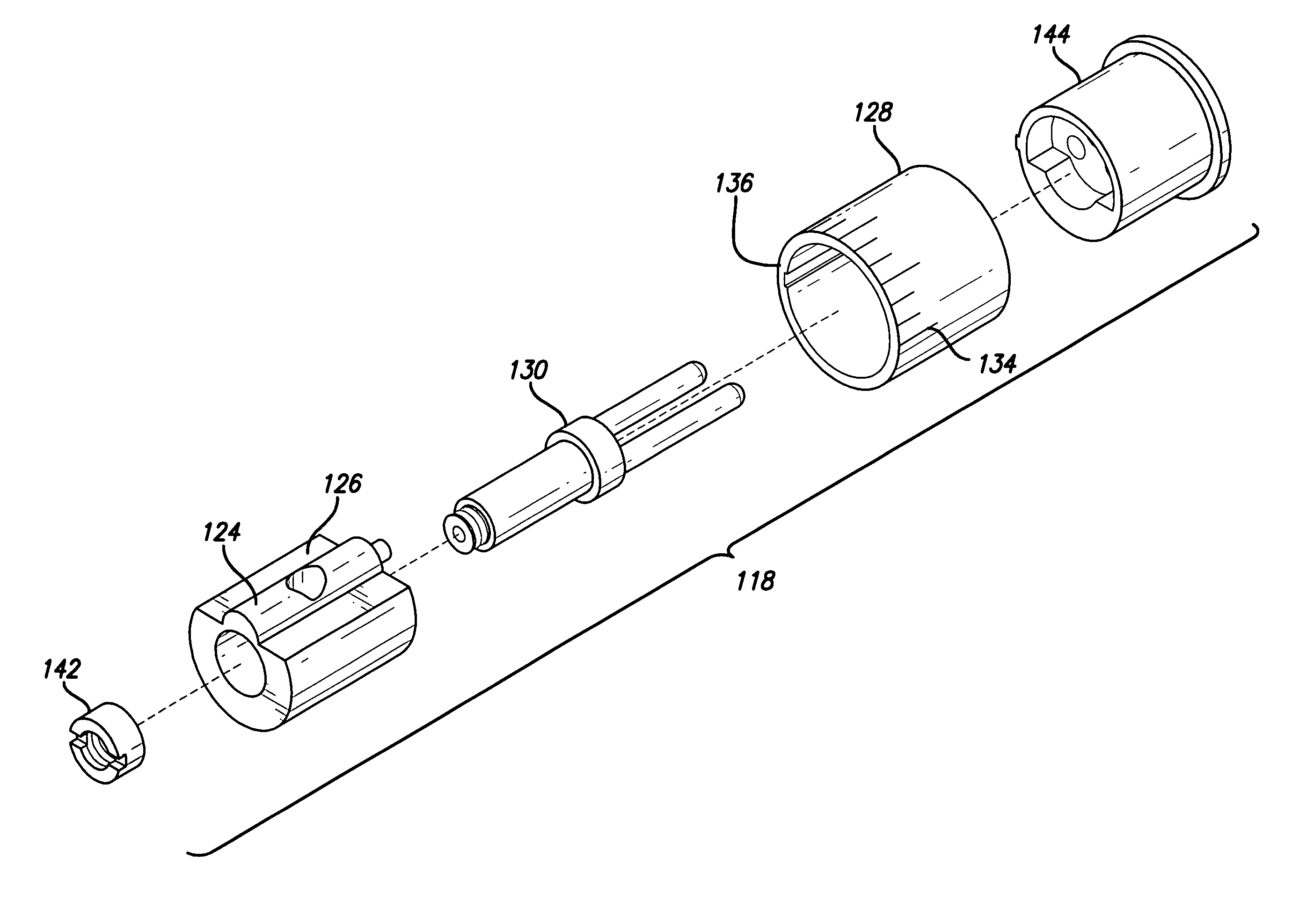
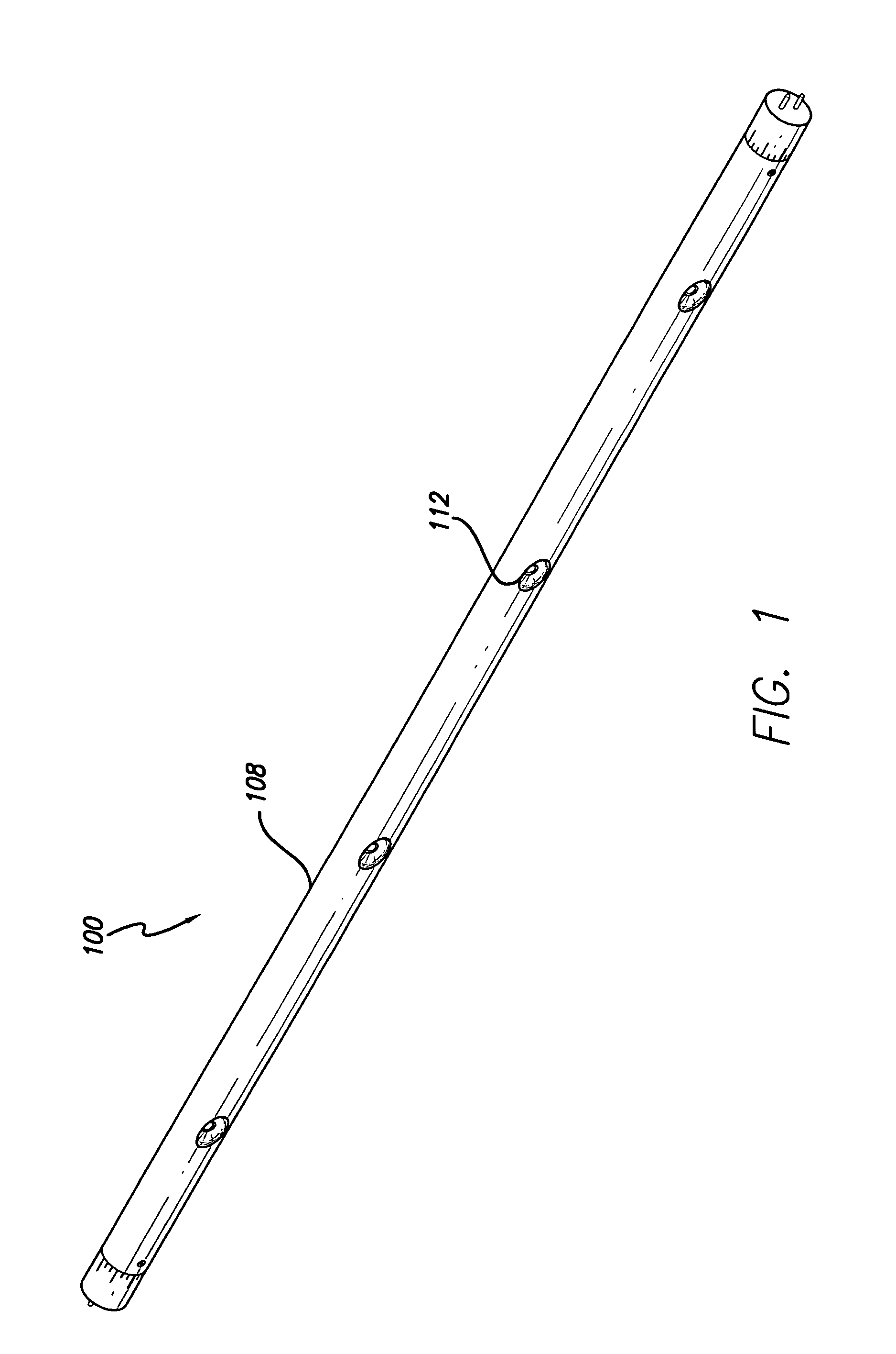
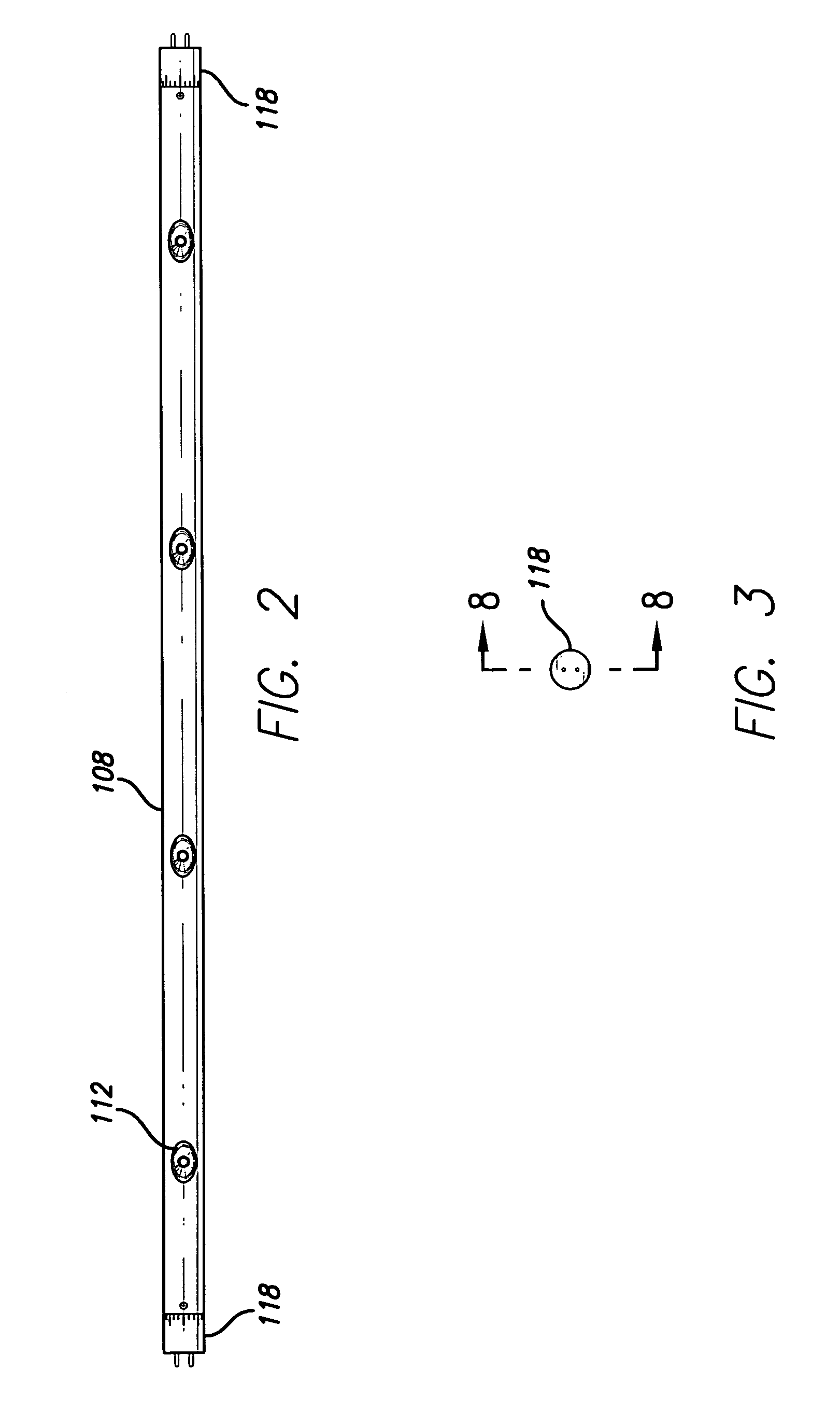
[0023]Referring to the figures, the LED lighting tube 100 includes a plurality of segments. For ease of description, an embodiment having two such segments, a first segment 102 and a second segment 104, is described here. The LED lighting tube 100 also includes a rotating connector 106 between the first segment 102 and the second segment 10...


PUM


Abstract

An LED lighting tube having a first segment, a second segment, and a rotating connector between the segments. Each segment has an elongated cylindrical housing, an aperture in the sidewall of the cylindrical housing, a reflector centered within the aperture, a circuit board within the cylindrical housing, and a rotatable electrical coupling connected to an outer end of the cylindrical housing. The circuit board has an LED that aligns with the aperture. The rotatable electrical coupling has a limiter insert that provides a rotative stop, a collet that at least partially surrounds the limiter insert and is rotatable about the limiter insert, and an interface connector secured to the limiter insert and in electrical communication with the circuit board. The rotatable electrical coupling permits the LED lighting tube to connect to a light fixture while also permitting the cylindrical housing to rotate relative to the light fixture. The rotation of the collet about the limiter insert is limited by the rotative stop.

Description

TECHNICAL FIELD[0001]This invention relates to LED lighting for use in existing fixtures, particularly fluorescent light fixtures.BACKGROUND ART[0002]Although fluorescent lights have been a staple in industrial, commercial, and residential lighting for some time, recent developments with light emitting diodes (LED) provide benefits over standard fluorescent systems. For example, LED systems feature low energy consumption, long lamp life, and reduced maintenance costs. In addition, LED give off no infrared or ultraviolet light and contained no mercury or PCBs.[0003]Existing devices directed to replacing florescent systems with LED have several shortfalls that are addressed by the current invention. For example, the current inventive device is designed to integrate into existing standard linear fluorescent fixtures. The segments of the lamp are also able to rotate for precise aiming of the LED, and this rotation is limited to prevent over-rotation and associated problems. Moreover, th...

Claims


Application Information

Patent Timeline
Patent Type & Authority Patents(United States)
IPC IPC(8): F21S4/00
CPCF21K9/17F21K9/58F21V17/02F21V19/008F21V21/30F21Y2101/02F21Y2103/003F21K9/272F21K9/65F21Y2103/10F21Y2115/10F21K9/27
Inventor BARTON, DANBARTON, BRAD
Owner RELED SYST
Why Eureka
Try Eureka