Fiber distribution hub

a fiber distribution and hub technology, applied in the field of fiber distribution hubs, can solve the problems of increasing network reliability, reducing network complexity and/or cost, and achieving the effect of enhancing access and scalability

Active Publication Date: 2011-11-29
COMMSCOPE TECH LLC
View PDF201 Cites 12 Cited by
  • Summary
  • Abstract
  • Description
  • Claims
  • Application Information

AI Technical Summary

Benefits of technology

Certain aspects of the disclosure relate to enhanced access and scalability through the use of modular components, such as modular subscriber termination components.

Problems solved by technology

The absence of active electronic devices may decrease network complexity and / or cost and may increase network reliability.

Method used


Image

  • Fiber distribution hub
  • Fiber distribution hub
  • Fiber distribution hub

Examples


Embodiment Construction

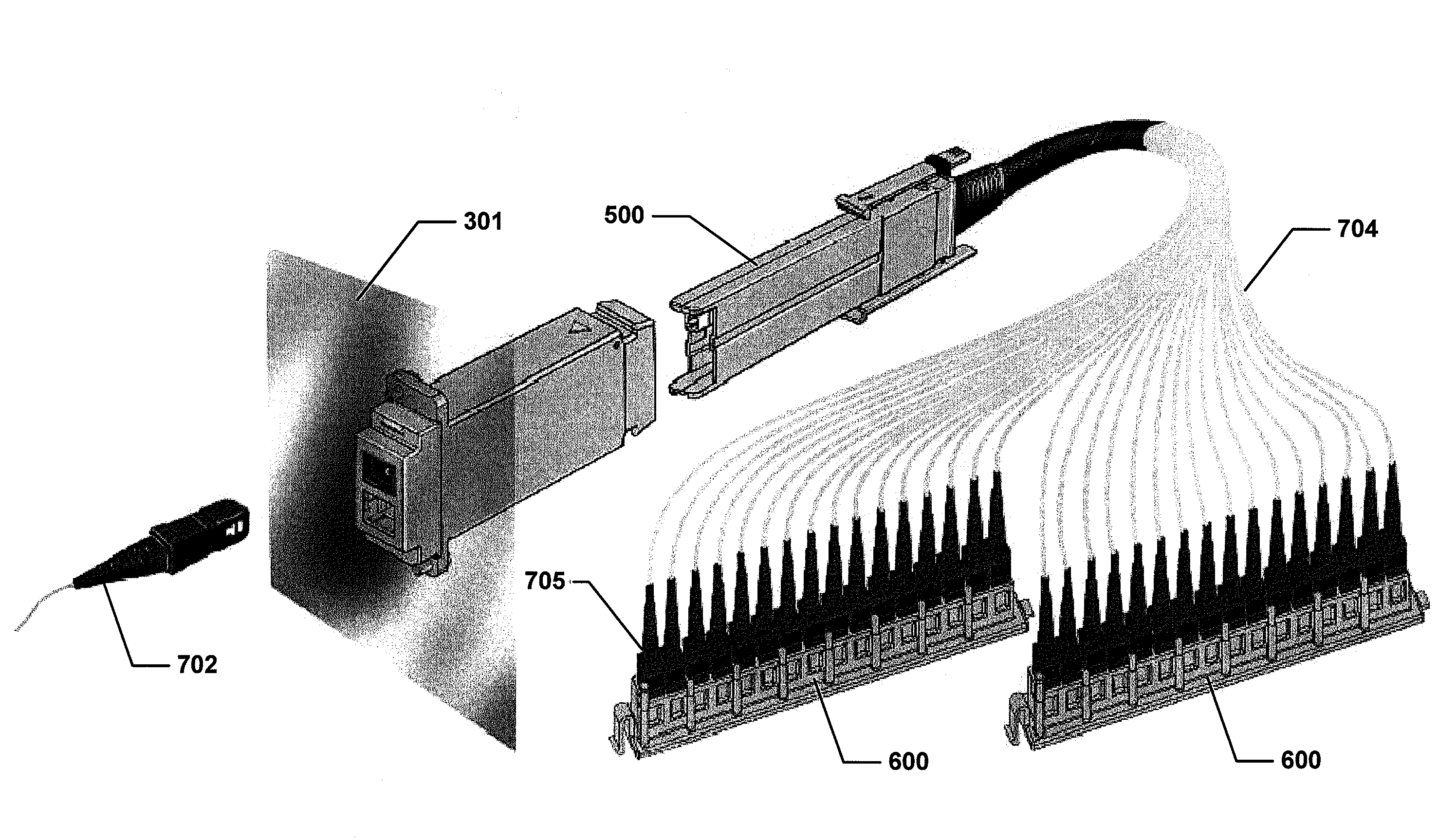
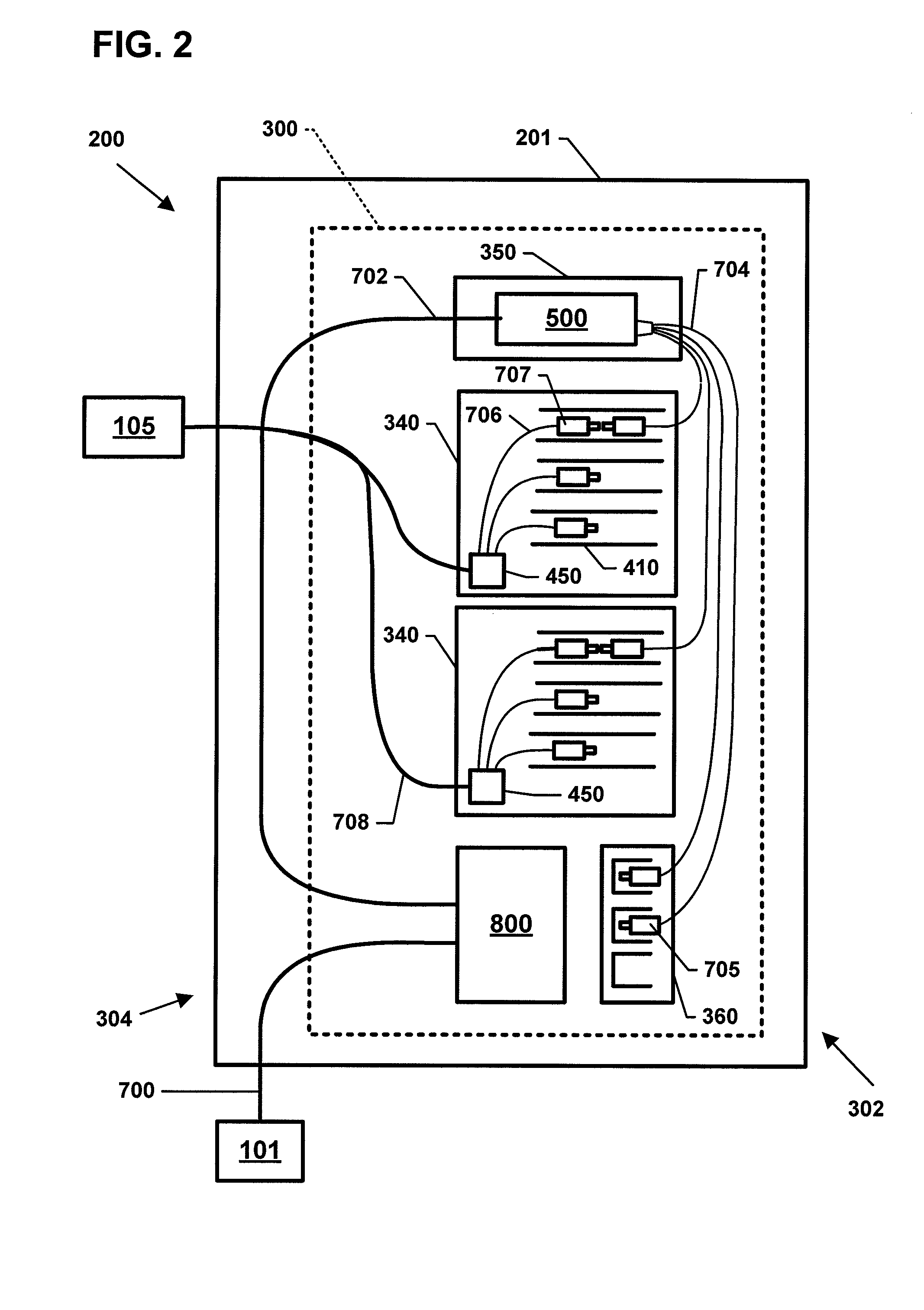
Referring now to FIGS. 2-6, example fiber distribution hubs (FDH) 200 having features that are examples of inventive aspects in accordance with the principles of the present disclosure are shown. Generally, a FDH 200 includes a cabinet 201 (FIG. 3) that houses internal components. The cabinet 201 is configured to receive a feeder cable (e.g., or F1 cable) 700 and a subscriber cable 708 (see FIG. 2).

In certain embodiments, a swing frame 300 (FIG. 2) is pivotably mounted (e.g., on hinges) within the cabinet 201. The swing frame 300 includes a bulkhead 301 (FIG. 11) that divides the swing frame 300 into a front portion 302 (see FIG. 4) and a back portion 304 (see FIG. 11). The bulkhead 301 includes a termination region 340, a splitter region 350, and a storage region 360 (see FIG. 2). In other embodiments, however, the termination region 340, splitter region 350, and storage region 360 can also be fixedly located within the cabinet 201. In some embodiments, the bulkhead 301 also includ...


PUM


Abstract

A fiber distribution hub includes a cabinet; a termination region positioned within the interior of the cabinet; at least one termination module mounted in at least one opening defined at the termination region; fiber optic connectors coupled to termination adapters of the termination module; intermediate fibers extending rearwardly of the fiber optic connectors; and a multi-fiber connector terminating the intermediate fibers. The termination module includes a housing enclosing the termination adapters. One or more termination modules can be incrementally added to the fiber distribution hub.

Description

BACKGROUNDPassive optical networks are becoming prevalent in part because service providers want to deliver high bandwidth communication capabilities to customers. Passive optical networks are a desirable choice for delivering high-speed communication data because they may not employ active electronic devices, such as amplifiers and repeaters, between a central office and a subscriber termination. The absence of active electronic devices may decrease network complexity and / or cost and may increase network reliability.FIG. 1 illustrates a network 100 deploying passive fiber optic lines. As shown, the network 100 can include a central office 101 that connects a number of end subscribers 105 (also called end users 105 herein) in a network. The central office 101 can additionally connect to a larger network such as the Internet (not shown) and a public switched telephone network (PSTN). The network 100 can also include fiber distribution hubs (FDHs) 103 having one or more optical splitt...

Claims


Application Information

Patent Timeline
Patent Type & Authority Patents(United States)
IPC IPC(8): G02B6/00
CPCG02B6/4452
Inventor REAGAN, RANDYMILLEA, KEITHLEBLANC, TOM
Owner COMMSCOPE TECH LLC
Why Eureka
Try Eureka