Robotic arms with coaxially mounted helical spring means

a technology of helical springs and robotic arms, applied in the field of robotic arms, can solve the problems of increasing system complexity, adding complexity and cost of manufacture, and reducing the cost of manufacturing, so as to reduce the cost, reduce the cost, and reduce the rotary movement of links.

Active Publication Date: 2011-12-06
OLIVER CRISPIN ROBOTICS
View PDF11 Cites 30 Cited by
  • Summary
  • Abstract
  • Description
  • Claims
  • Application Information

AI Technical Summary

Benefits of technology

[0010]Where the links within a segment are maintained under compression by actuator means such as control cables, the spring means may be arranged to apply tension to the links within the segment to reduce friction between the links while maintaining the torsional stiffness of the segment. Alternatively, the spring means may be arranged so as to maintain the links under compression in order to reduce the load in the actuator means and hold the arm together. In this case, the arm may retain its shape even when the actuator means does not exert a load on them.
[0014]In an alternative embodiment, the spring means may be disposed internally of the link assembly. It will be appreciated by the person skilled in the art that various combinations of springs may be used, for example, a plurality of springs may be provided externally of the links to provide an effective cladding for the arm, or a combination of internal springs and external springs maybe provided, the characteristics of each spring being selected so as to impart predetermined characteristics upon the arm. Thus, for example, by selecting a suitable combination of spring or springs the arm may adapt more readily to the particular purpose for which the arm is ultimately to be employed.
[0017]In another aspect of the invention, the unloaded pitch of the spring may be slightly longer or shorter than the pitch of the engagement means on the links so that as the links are sequentially rotationally engaged with the spring, the arrangement is such that the spring will urge adjacent links apart or together. If they are urged apart, this reduces any applied compressive load at the interface between adjacent links. If urged together, this helps to ensure that the links engage correctly during use. Should excessive force cause the links to disengage, the spring will cause them to re-engage on removal of the force, such that the arm is resilient to damage.
[0022]In general, it is preferred that there should be approximately one or more complete wraps or coils of the helix of the spring between attachment points on adjacent links. Shortening this, results in an arm with a reduced ability to bend, while lengthening it increases the potential flexibility. The person skilled in the art will further appreciate that if substantially less than one complete coil or wrap of spring is free to move between adjacent links, the helix may be over-constrained and may experience substantially higher stresses than if at least one complete coil of the spring is free to move between the attachment point on adjacent links.
[0029]In another embodiment, three or more springs of the same diameter may be used with each link attached to all of the springs by any of the means herein described. In another embodiment, combinations of two or more differently handed springs or sets of springs of equal diameter may be used with each link attached to all of the springs such that the rotary movement of a link with respect to one spring would result in a change in tension or compression in another spring, said change in tension serving to constrain further rotary movement of the links one with respect to another.
[0030]The present invention enables the undoubted benefits of the “snake arm” to be incorporated in much smaller devices, which are therefore capable of working in a much more restricted environment. Furthermore, the arm construction in accordance with the present invention permits of a more simplified structure than hitherto thus enabling more rapid and simplified construction and hence a significant reduction in cost.

Problems solved by technology

In a multi-link segment arm, these friction losses build up and the overall friction losses to be overcome during manipulation of the arm can be considerable.
While successful in achieving its object, this further adds to the complexity of the system and hence to the complexity and cost of manufacture.
While this arrangement is eminently satisfactory, it does again add to the complexity of construction.

Method used


Image

  • Robotic arms with coaxially mounted helical spring means
  • Robotic arms with coaxially mounted helical spring means
  • Robotic arms with coaxially mounted helical spring means

Examples


Embodiment Construction

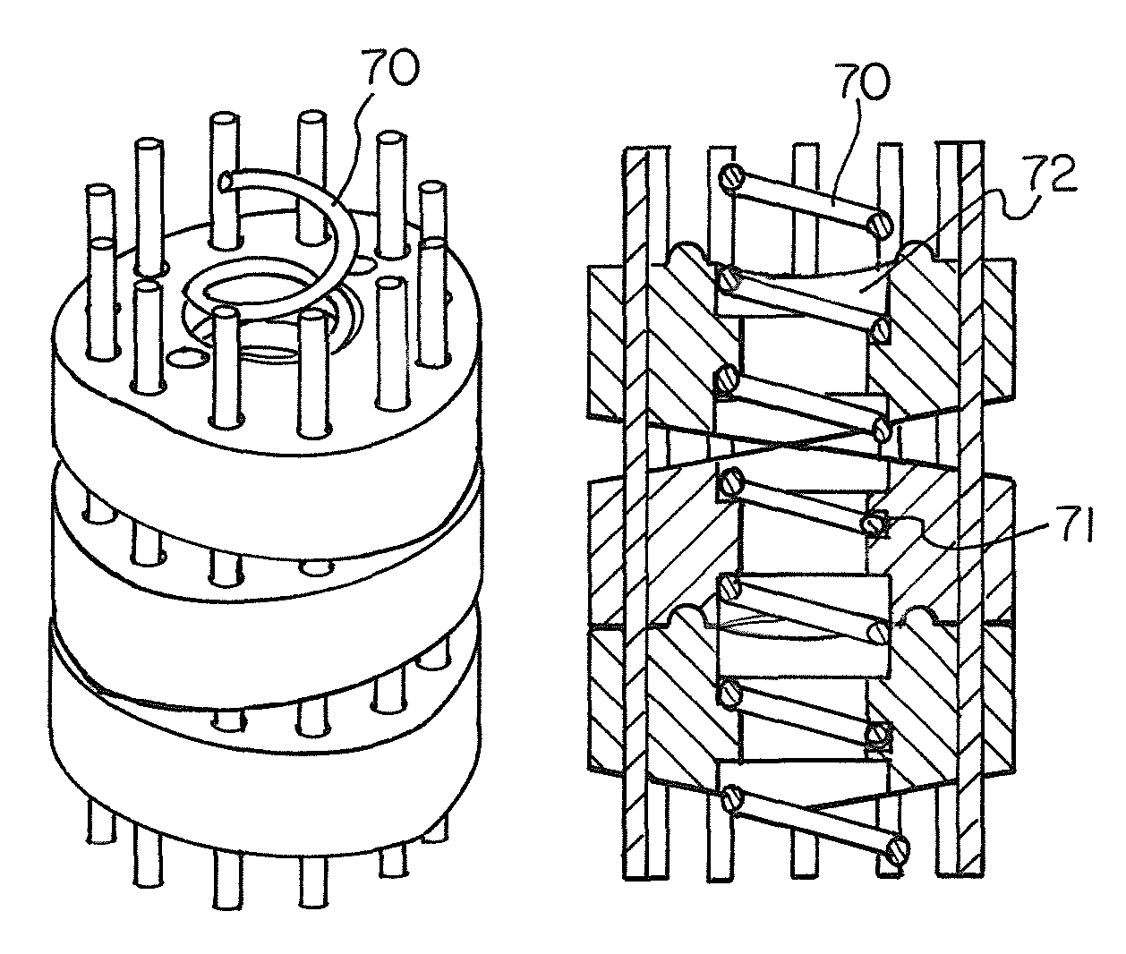
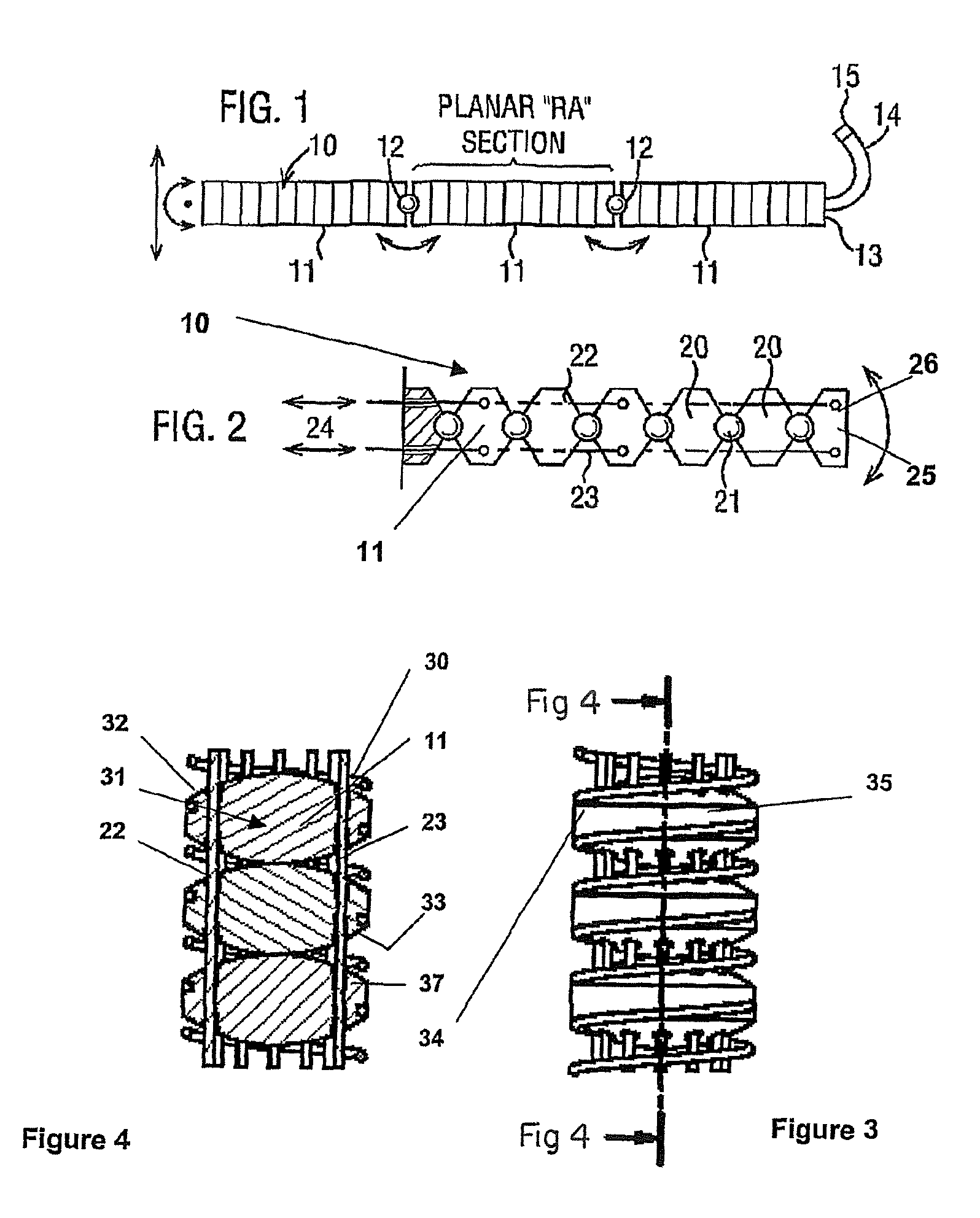
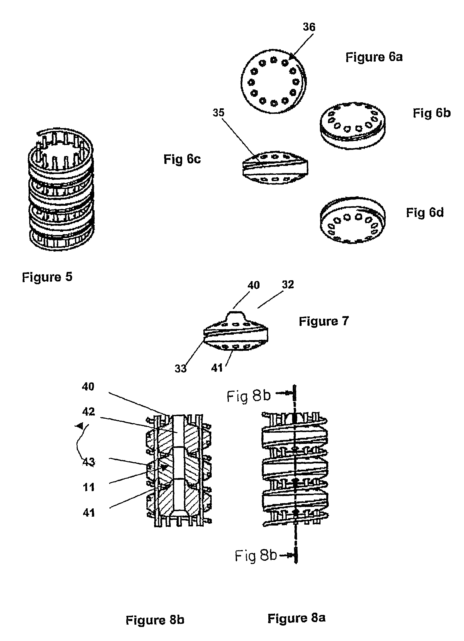
[0060]Referring to FIGS. 1 & 2, the arm as shown comprises three segments 10, each segment 10 comprising a plurality of link elements 11. Each segment 10 is connected to its neighbour by means of an articulated joint 12. The distal end 13 of the arm carries a work head 14 incorporating a tool 15. Each plurality of link elements may comprise an end cap 11′ to engage with the first and last links of the segment and with the spring to contain rotation of the links with respect to the spring.

[0061]Each individual link 11, is capable of limited movement with respect to its neighbour by virtue of an articulated joint 21 (see FIG. 2) and the segment 10 as a whole is controlled by means of control wires and 22 and 23 which extended through each of the intermediate links 11 and is fixedly attached to the end element 25 of segment 10. Each of the control wires extends to actuator means indicated generally at 24 in FIG. 2, which actuator means can be controlled to provide varying tensions to e...


PUM


Abstract

A robotic arm comprising a plurality of segments, each comprising articulated links, and means for causing each segment to bend so the arm can follow a serpentine path. A helical spring is provided coaxially with the arm to urge the links to an initial datum position, and to distribute the bending over the links of each segment.

Description

CROSS-REFERENCE TO RELATED APPLICATIONS[0001]The present application is a continuation of pending International patent application PCT / GB2007 / 000034 filed on Jan. 8, 2007 which designates the United States and claims priority from GB patent application 0600170.5 filed on Jan. 6, 2006, the content of which is incorporated herein by reference.FIELD OF THE INVENTION[0002]This invention relates to robotic arms, and has particular reference to a robotic arm having one or more controllable segments of which comprises a plurality of links, each of which links is articulated with respect to its neighbour thereby allowing each segment to bend.BACKGROUND OF THE INVENTION[0003]Our co-pending application WO02 / 016995, the disclosure of which is incorporated herein by reference, describes and claims such an arm. The arm has a work head adapted to carry a tool or examination element for work or examination at a site, and operating means for operational control of the work head. The arm is adapted ...

Claims


Application Information

Patent Timeline
Patent Type & Authority Patents(United States)
IPC IPC(8): B25J17/00
CPCB25J9/06B25J9/104B25J18/06Y10T74/20323A61B2019/2238A61B2034/306
Inventor BUCKINGHAM, ROBERT OLIVERGRAHAM, ANDREW CRISPIN
Owner OLIVER CRISPIN ROBOTICS
Why Eureka
Try Eureka