Load-bearing resilient mount

a resilient, load-bearing technology, applied in the field of mounts, can solve the problems of frequent replacement, high cost, time-consuming, etc., and achieve the effect of limiting the deformation of the stiffening elemen

Active Publication Date: 2011-12-06
CATERPILLAR INC
View PDF15 Cites 22 Cited by
  • Summary
  • Abstract
  • Description
  • Claims
  • Application Information

AI Technical Summary

Benefits of technology

[0008]In accordance with yet another aspect, the present disclosure is directed toward a resilient mount comprising a first mounting member, a second mounting member, and a first plurality of stiffening elements located between the first and second mounting members. At least a first stiffening element of the first plurality of stiffening elements may be non-parallel to a second stiffening element of the first plurality of stiffening elements. Each of the first plurality of stiffening elements may have a material thickness and an out-of-plane dimension, which is greater than the material thickness. Each stiffening element of the first plurality of stiffening elements may be substantially rigid so as to substantially limit the deformation of the stiffening element under load. The mount may also include a resilient material located between and coupled to adjacent stiffening elements of the first plurality of stiffening elements.

Problems solved by technology

However, they are prone to premature failure in the highly elastomeric material to the embedded flat rings could result in the need to frequently replace these load-bearing suspension mounts.
Replacement is typically difficult, time-consuming, and expensive.

Method used


Image

  • Load-bearing resilient mount
  • Load-bearing resilient mount
  • Load-bearing resilient mount

Examples


Embodiment Construction

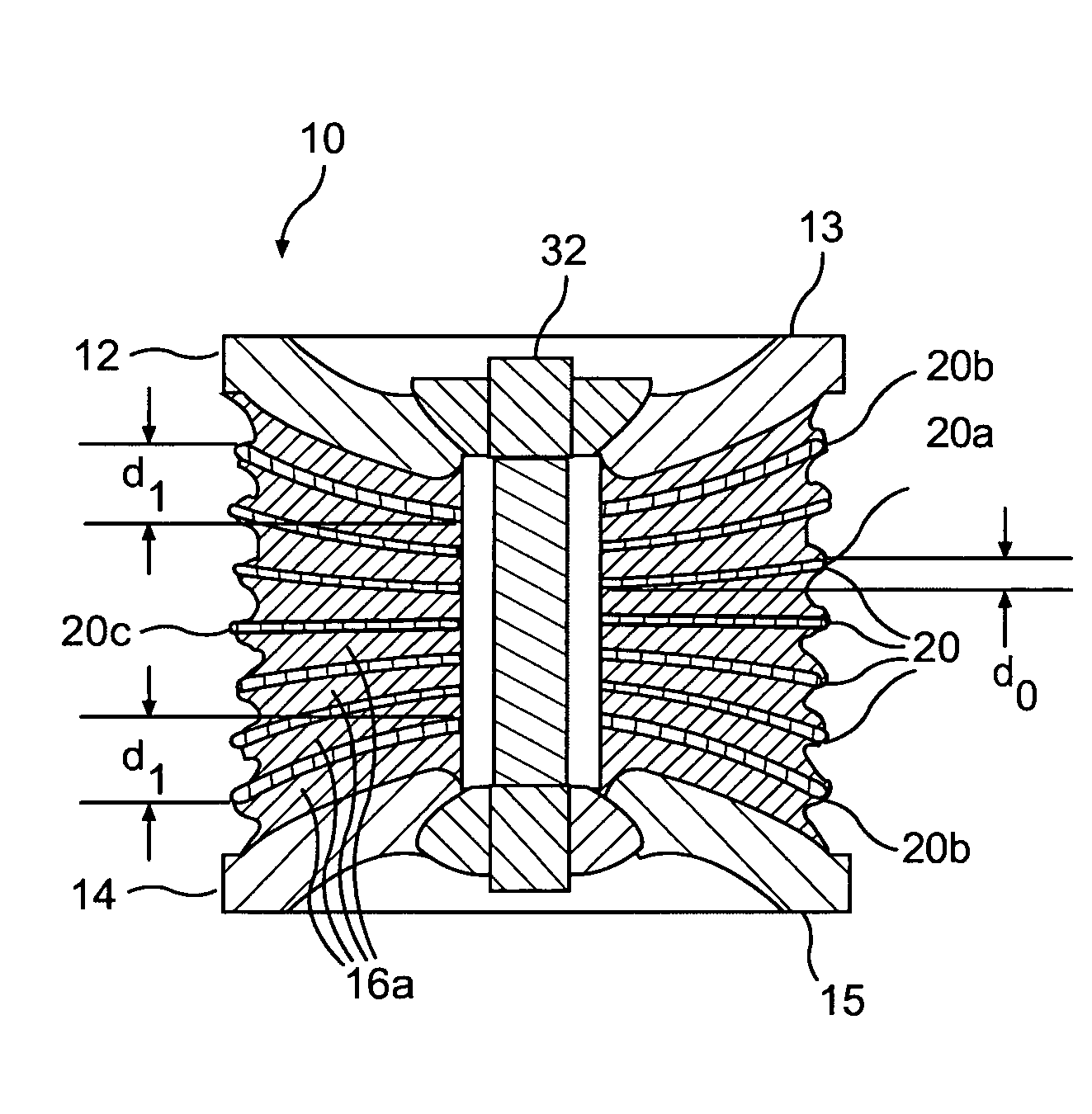
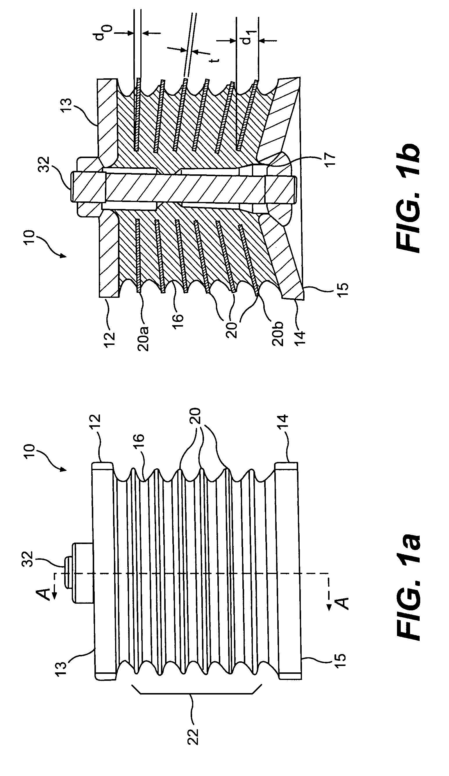
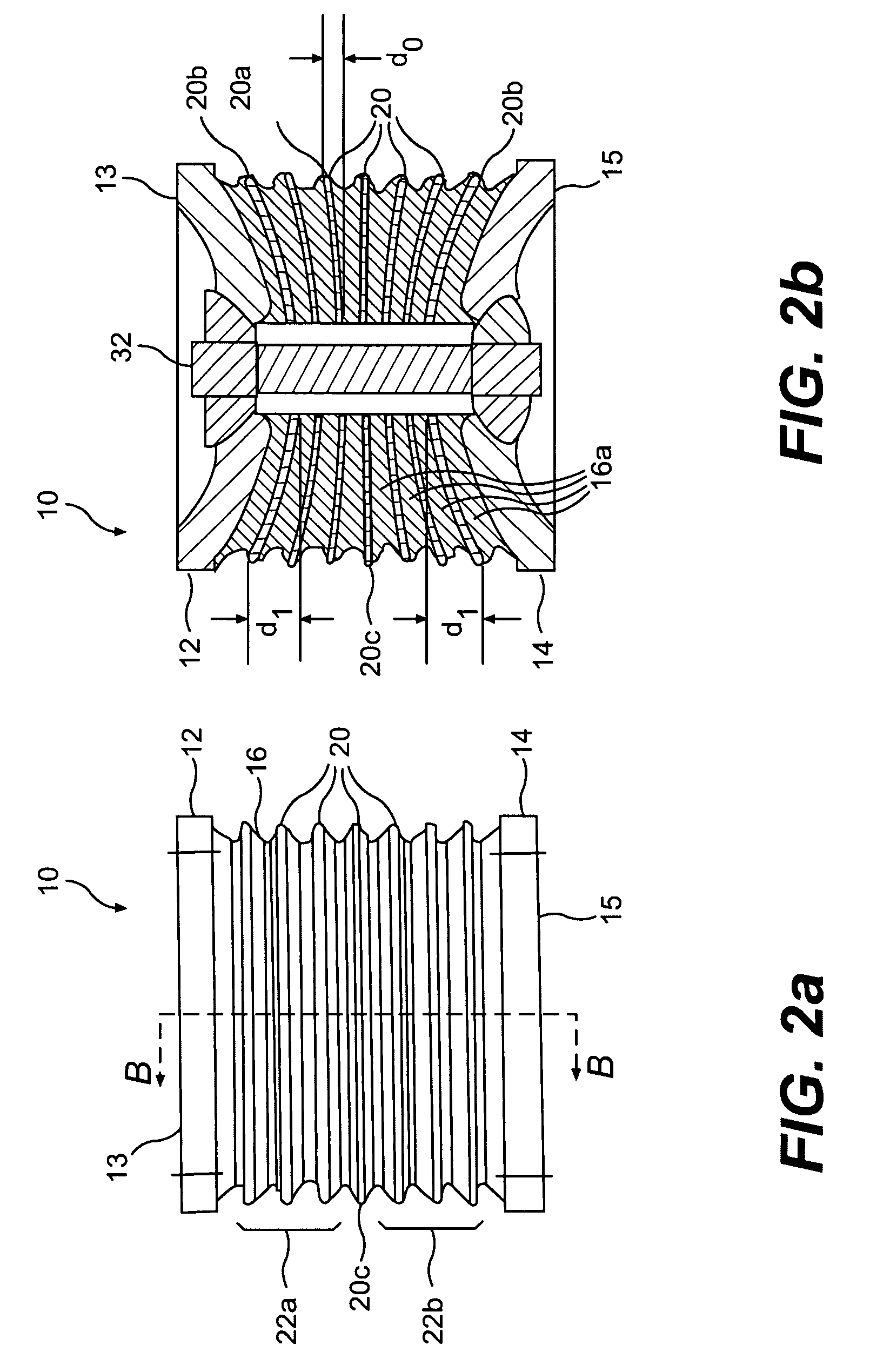
[0016]FIGS. 1a and 1b are illustrations of an exemplary embodiment of a resilient mount 10 in accordance with certain disclosed embodiments. Resilient mount 10 includes a first mounting member 12 and a second mounting member 14. A resilient material 16 is provided between first and second mounting members 12, 14, and a plurality 22 of stiffening elements 20 are embedded in the resilient material 16. Resilient mount 10 would typically be positioned between two machine or vehicle components (not shown).

[0017]Both first mounting member 12 and second mounting member 14 may be flat plates having square, rectangular, circular, or other regular or irregular-shaped perimeters. Alternatively, one or both of first and second mounting members 12, 14 may be non-planar, for example, concave, as best shown by second mounting member 14 in FIG. 1b, convex, or other regular or irregular non-planar shapes. First and second mounting members may be provided with a central through hole 17.

[0018]Addition...


PUM


Abstract

A resilient mount including a first mounting member and a second mounting member is provided. The mount includes a first plurality of stiffening elements located between the first and second mounting members. At least a first stiffening element of the first plurality of stiffening elements is non-parallel to a second stiffening element of the first plurality of stiffening elements. Each of the first plurality of stiffening elements has a material thickness and an out-of-plane dimension that is greater than the material thickness. Each stiffening element of the first plurality of stiffening elements is substantially rigid so as to substantially limit the deformation of the stiffening element under load. The mount may also include a resilient material located between and coupled to adjacent stiffening elements of the first plurality of stiffening elements.

Description

[0001]This application is a continuation-in-part of U.S. patent application Ser. No. 10 / 317,211, filed Dec. 12, 2002 now U.S. Pat. No. 7,201,367, the entire contents of which are hereby incorporated by reference.TECHNICAL FIELD[0002]The present disclosure relates generally to a mount, and, more particularly, to a resilient mount capable of carrying loads while its mounting surfaces move relative to one another.BACKGROUND[0003]Mountings with both load bearing and deflection capabilities have been used in the suspension systems of vehicles for many years. In some applications, load bearing suspension mounts, such as elastomeric mounts, are positioned between two vehicle components. These elastomeric mounts are designed to carry compressive and tensile loads, while at the same time allowing the two vehicle components to translate and tilt relative to one another. Typically, an elastomeric mount includes a pad of an elastomeric material, for example, rubber, sandwiched between two mount...

Claims


Application Information

Patent Timeline
Patent Type & Authority Patents(United States)
IPC IPC(8): F16F7/00B60G11/22F16F1/371F16F1/40
CPCB60G11/22F16F1/371F16F1/403B60G2202/1422B60G2202/143F16F2228/08
Inventor WIETHARN, ROSS PAUL
Owner CATERPILLAR INC
Why Eureka
Try Eureka