Trigger switch

a trigger switch and switch technology, applied in the direction of electric switches, basic electric elements, electric apparatus, etc., can solve the problems of requiring a tightening process, affecting the effect of the brush, and removing the contact element from the support member

Active Publication Date: 2011-12-06
SATORI ELECTRIC
View PDF3 Cites 18 Cited by
  • Summary
  • Abstract
  • Description
  • Claims
  • Application Information

AI Technical Summary

Benefits of technology

[0009]Accordingly, it is a first object of the present invention to provide a trigger switch in which a movable contact element moving swingably does not easily come off from a support member. Further, it is a second object to provide a trigger switch that permits dust accumulated inside the trigger to be expelled to the outside easily. Further, it is a third object to provide a trigger switch having a cover opening portion to permit a control device to be mounted integrally with a switch, in which dust intruding from the opening portion does not easily intrude into the movable contact element side that is a switch mechanism.
[0012]Another trigger switch according to the present invention switches the state of a switch mechanism mounted inside a case based on a sliding manipulation of a trigger. A control device is disposed under the condition where the control device is exposed from the outer wall surface of a cover that covers the case. Dustproof walls are mounted between a first chamber where the control device is disposed and a second chamber constituting the switch mechanism to keep out dust.
[0014]In the present invention, the auxiliary brush is interposed in the movable contact element moving swingably. The auxiliary brush is engaged in the opening portion formed in the support member. The movable contact elements are supported swingably. The movable contact elements do not easily come off from the support member during assembly and during use. It is assured that the movable contact elements swing stably. During swinging motion, the movable contact elements are prevented from bounding; otherwise, an are would be induced across the contacted portion and poor contact would be made.
[0015]The trigger has a space in addition to the opening portions in which ribs are engaged. The space is formed in bottom and top portions and in communication with the opening portions. Therefore, dust produced when the ribs are engaged in the opening portions can be expelled to the outside via the space in communication with the opening portions. Consequently, accumulation of dust inside the bigger can be avoided. The problem that the trigger cannot be pulled to its full stroke can be prevented.
[0016]In addition, an opening portion is formed to permit a control device mounted in the cover to be opened. Dustproof walls are mounted at a position located on one side of the opening portion. In consequence, dust intruding from the opening portion can be prevented from intruding to the switch mechanism side.
[0017]Yet further, the switch mechanism and the FET accommodation portions are made independent of each other. Consequently, the switch mechanism can be prevented from being affected by heat generated from the FET.

Problems solved by technology

Consequently, there is such a problem that the contact element comes off from the support member during use.
This would produce poor contact.
However, to hold the brush, a process for tightening the brush is required.
This produces a problem that the cost is increased.
Under this condition, the trigger cannot be pulled to its full stroke, thus presenting a problem.
In spite of this contrivance, a problem takes place.
However, there is the problem that dedicated packing or the like is necessary, increasing the cost.
Furthermore, the conventional product has the problem that heat from the FET stays inside the switch because the switch mechanism and the portion accommodating the FET are integrated.

Method used


Image

  • Trigger switch
  • Trigger switch
  • Trigger switch

Examples


Embodiment Construction

[0047]Trigger switches according to embodiments of the present invention are hereinafter described in detail with reference to the drawings.

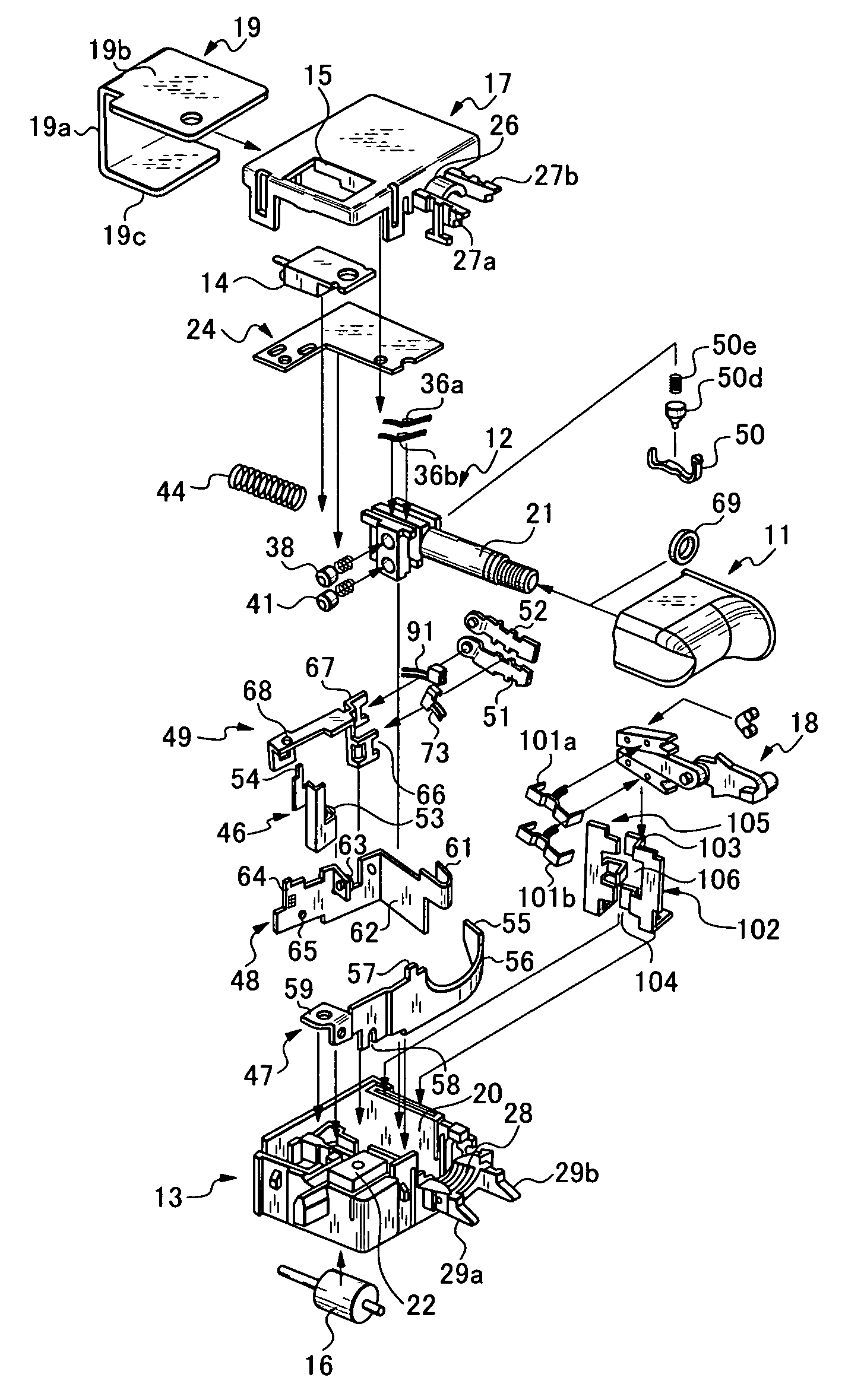
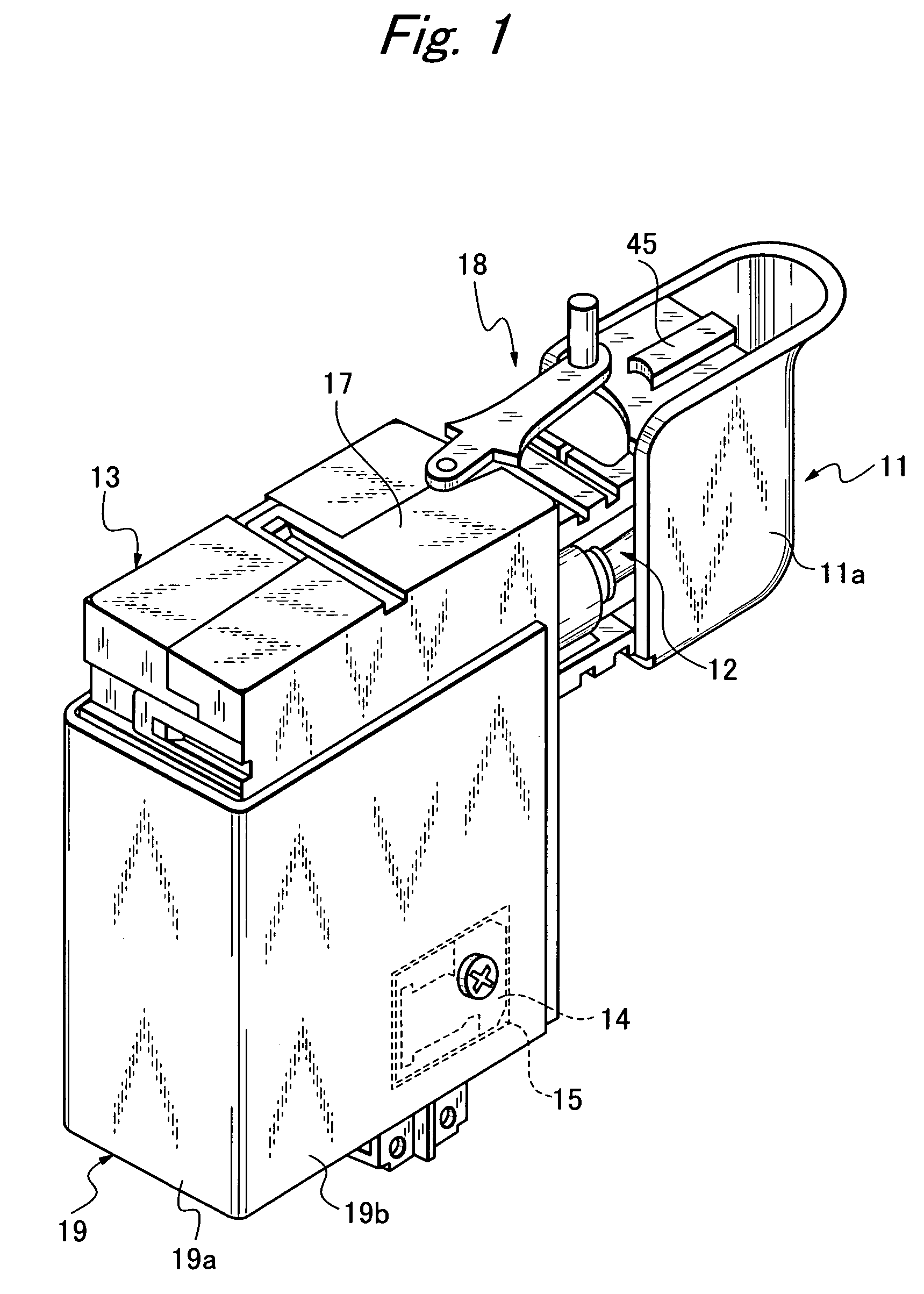
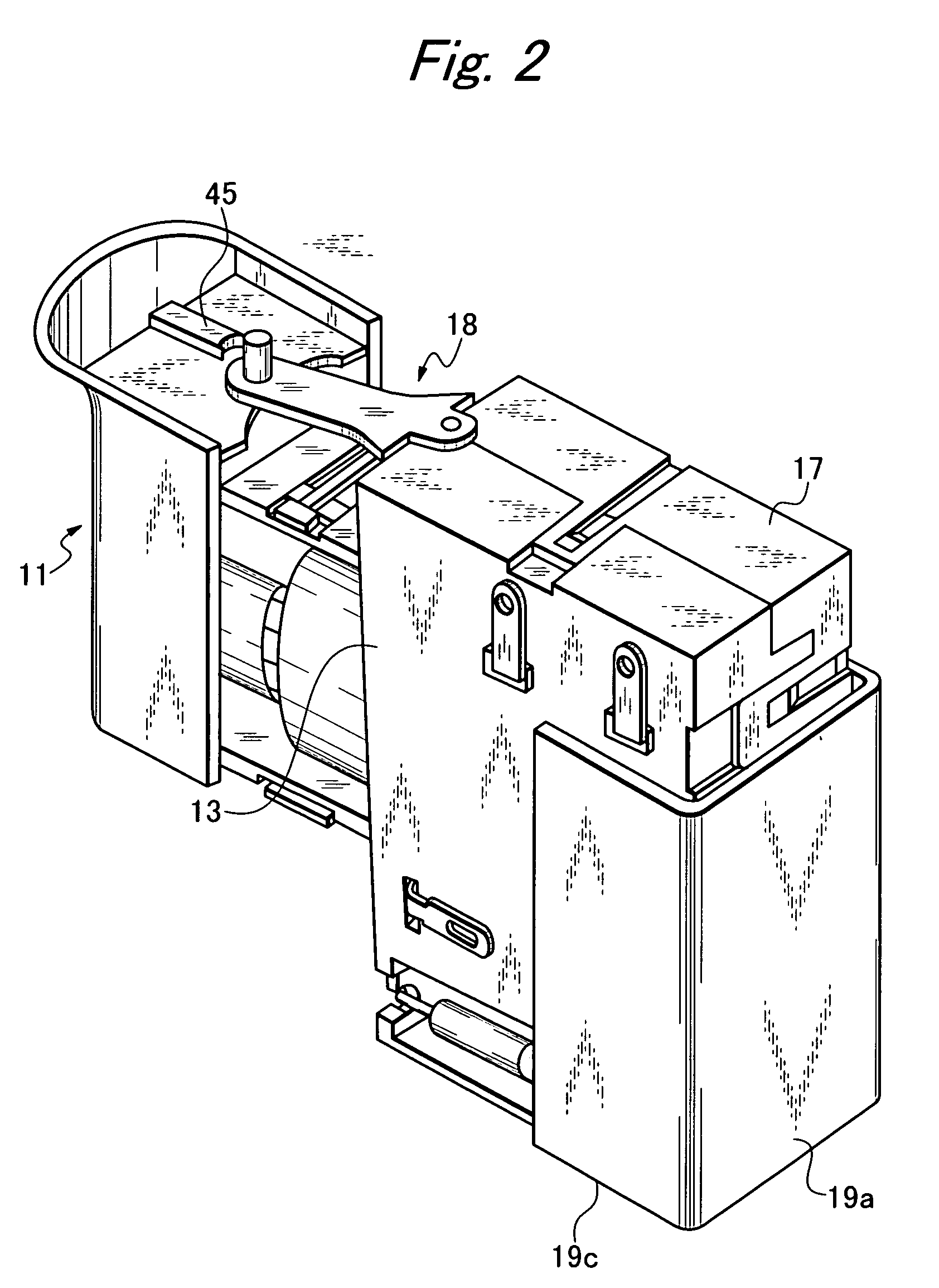
[0048]A trigger switch according to an embodiment of the present invention is shown in FIGS. 1, 2, and 3. The trigger switch has a vertically elongated box-like form, and has a case 13, a cover 17, a bigger 11 capable of being manipulated by hand fingers, a switching control portion 18 mounted on the top surface of the case 13 and acting to switch the direction of the rotation of a motor, and a heat-dissipating plate 19 disposed at the position of the outer periphery of the cover 17 mounted over the case 13. A sliding control device 12 for transferring an external manipulating action from the trigger 11 is mounted at a higher position in the case 13, which has an open side surface. A switch mechanism is incorporated in the case 13. The cover 17 doses the open surface at the side of the case 13 and has an open portion 15 to cause a control device...


PUM


Abstract

A trigger switch has an insulative enclosure, a movable contact element, and a sliding control device slidably mounted to the insulative enclosure. The insulative enclosure includes a case and a cover. The case has plural terminal subassemblies made of conductive metal members disposed therein. The case has an opening over which the cover is mounted. A fixed contact is mounted on one of the terminal subassemblies in the case. The movable contact element has a movable contact mounted at one end of the movable contact element and located opposite to the fixed contact. The movable contact element is swingably supported on another terminal subassembly. A trigger is mounted at one end of the sliding control device. An auxiliary brush is interposed in the movable contact element. A support member is provided with an opening portion in which the auxiliary brush is engaged such that the brush is swingably supported.

Description

BACKGROUND OF THE INVENTION[0001]1. Field of the Invention[0002]The present invention relates to a trigger switch and, more particularly, to improvements in a switch structure inside a trigger switch used in an electric power tool.[0003]2. Prior Art[0004]A conventional and known trigger switch is disclosed, for example, in JP-A-2003-109451. This trigger switch has a control device that is mounted to a case by an improved mounting mechanism. An attempt has been made to reduce the thickness while securing good dustproofness. To achieve this, the state of the switch mechanism inside the case of the trigger switch is switched based on a triggering manipulation. The switch mechanism is incorporated in the internal space of the case. The opening at one side of the case that is opened in a corresponding manner to the internal space of the case is covered and closed by a cover. The control device is accommodated in a concave accommodation portion formed in a part of the other side surface o...

Claims


Application Information

Patent Timeline
Patent Type & Authority Patents(United States)
IPC IPC(8): H01H13/02
CPCH01H9/04H01H9/061H01H13/06H01H2009/066
Inventor SATO, MANABU
Owner SATORI ELECTRIC
Why Eureka
Try Eureka