Mechanical Partial Desolventizing System and Process

a partial desolventization and mechanical technology, applied in the field of system and process, can solve the problems of not being able to effectively use a vacuum to pull additional solvent from the spent solids, and experience the concept, so as to save capital cost in addition to thermal energy and reduce energy cos

Inactive Publication Date: 2010-06-24
DESMET BALLESTRA NORTH AMERICA INC
View PDF25 Cites 3 Cited by
  • Summary
  • Abstract
  • Description
  • Claims
  • Application Information

AI Technical Summary

Benefits of technology

[0014]It has been determined that with light squeezing, solvent can be readily expelled from the spent solids after the extraction process, prior to the thermal desolventizing process. It has been further determined that various mechanical means exist which can separate the initial solvent from the spent solids using mechanically generated pressure, at a lower energy cost than the present state-of-the-art thermal desolventizing process. By removing a portion of the solvent in the spent material prior to thermal desolventizing, the indirect steam pre-desolventizing section of the desolventizing process can be significantly reduced in size to save capital cost in additional to thermal energy.

Problems solved by technology

However, this concept experienced two practical problems.
First, it was not possible to effectively use a vacuum to pull additional solvent from the spent solids due to the difficulty of maintaining a material seal in the drainer conveyor.
Secondly, the small amount of additional liquid that gravity drained (without the use of vacuum) contained a high solids content and plugged the pump suction.

Method used


Image

  • Mechanical Partial Desolventizing System and Process
  • Mechanical Partial Desolventizing System and Process
  • Mechanical Partial Desolventizing System and Process

Examples


Embodiment Construction

[0021]The invention will now be described in the following detailed description with reference to the drawings, wherein preferred embodiments are described in detail to enable practice of the invention. Although the invention is described with reference to these specific preferred embodiments, it will be understood that the invention is not limited to these preferred embodiments. But to the contrary, the invention includes numerous alternatives, modifications and equivalents as will become apparent from consideration of the following detailed description.

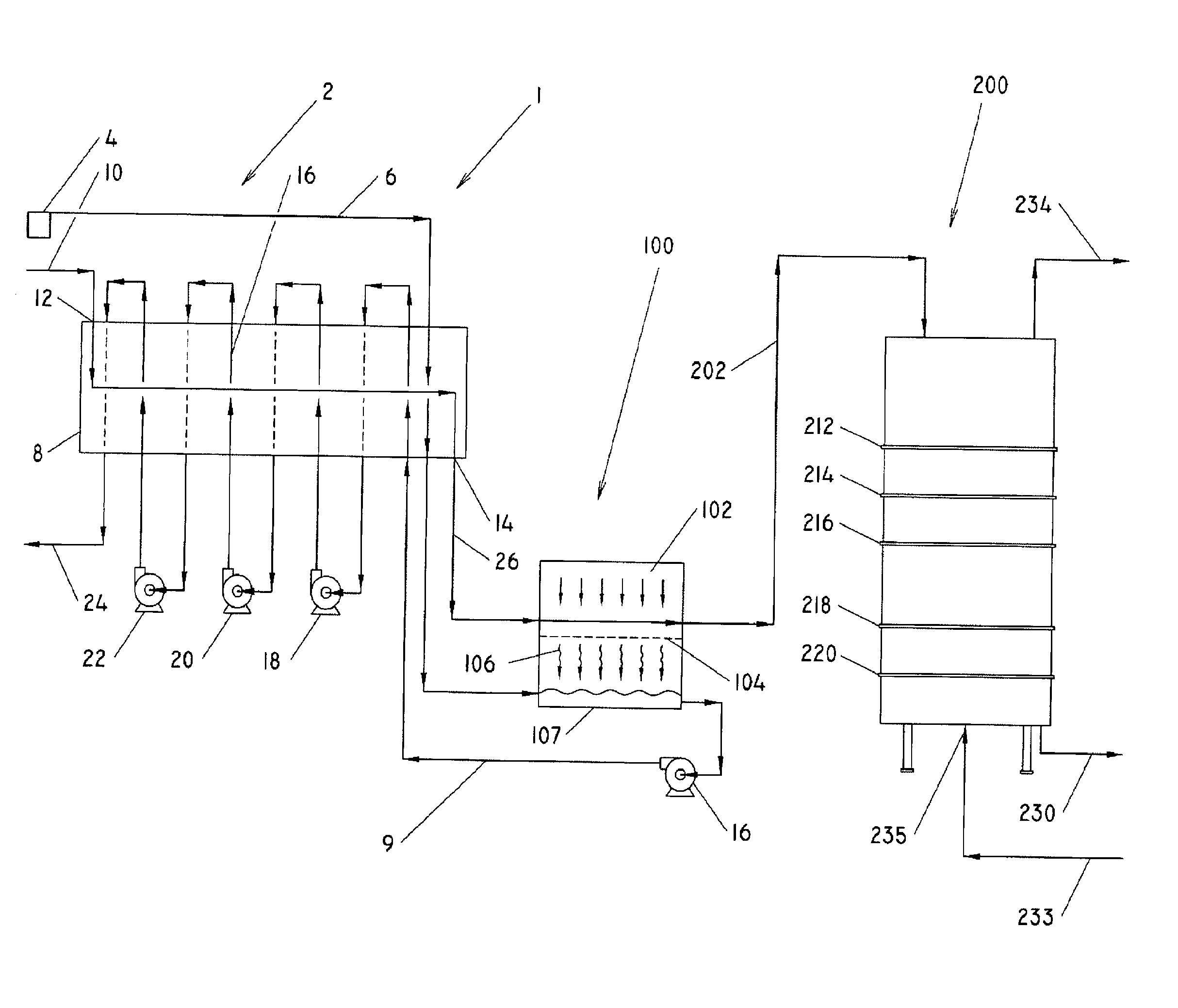
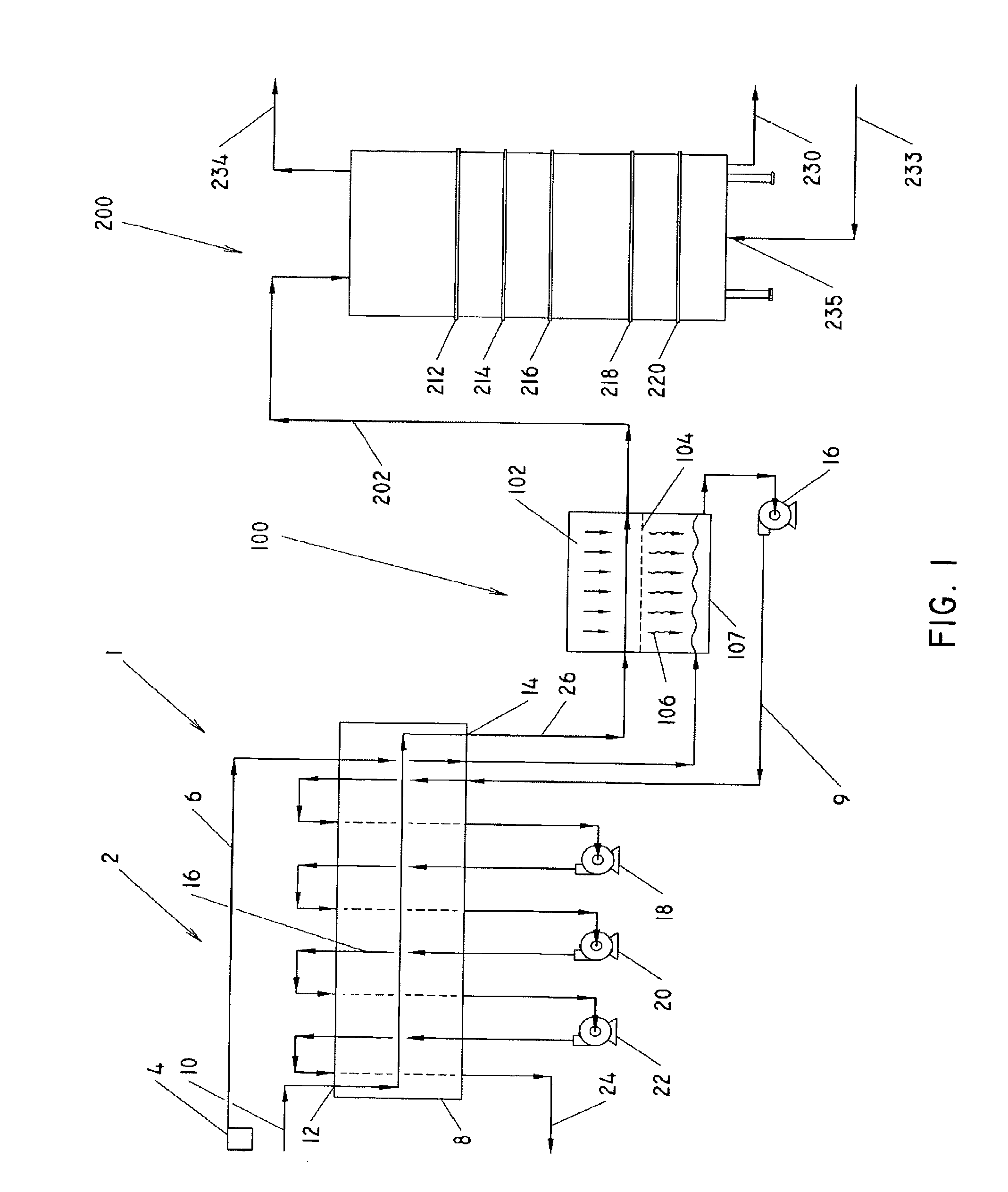
[0022]Turning now to FIG. 1, there is shown a schematic diagram illustrating an extraction and desoventizing system, indicated generally at 1, for use with oleaginous material. The system 1 has three primary components, namely an extraction apparatus 2, a mechanical partial desolventizing apparatus 100, and a thermal desolventizing apparatus 200. As will be described below, the system 1 extracts oil from oleaginous materials with a ...


PUM

PropertyMeasurementUnit
temperatureaaaaaaaaaa
weightaaaaaaaaaa

Abstract

Improved system and process for separating the initial portion of liquid solvent from spent oleaginous material after the solvent extraction process and prior to the thermal desolventizing process. Solvent laden solids departing the solvent extraction process are subjected to mechanical pressure to squeeze a portion of the liquid solvent through a perforated surface, into a collection hopper. This liquid solvent is subsequently recycled back to the solvent extraction process for liquid clarification and additional oil recovery.

Description

CROSS REFERENCE TO RELATED APPLICATION[0001]This application claims the priority benefit of U.S. Provisional Patent Application Ser. No. 60 / 734,628 filed Nov. 8, 2005.BACKGROUND OF THE INVENTION[0002]1. Field of Invention[0003]The invention relates a system and process for extracting oil from oleaginous materials and desolventizing the meal, and more specifically, a system and process incorporating a mechanical partial desolventizing apparatus and step.[0004]2. Description of Related Art[0005]It is well known in the art to extract oils and fats from oleaginous materials such as soybean flakes, rapeseed cake, sunflower cake, peanuts, sesame seeds, cotton seeds, and the like, by grinding the oleaginous material to form grains or flakes and then extracting the oil using a solvent extraction process. The edible oil fraction from the oleaginous material is separated from the protein-rich solid fraction by passing the solvent through the granular solid material to separate the extractable...

Claims


Application Information

Patent Timeline
Patent Type & Authority Applications(United States)
IPC IPC(8): C11B1/10B01D11/02
CPCC11B1/108C11B1/102
Inventor KEMPER, TIMOTHY G.
Owner DESMET BALLESTRA NORTH AMERICA INC
Why Eureka
Try Eureka