
Lining Plate for Lining of Moulding Chambers of Moulding Machines

a technology of moulding chamber and lining plate, which is applied in the direction of ceramic shaping lining, machine composition, printing, etc., can solve the problems of inability to meet the requirements of production, so as to improve the quality of production and reduce the cost. , the effect of improving the quality of production

Active Publication Date: 2011-12-01
DISA IND
View PDF35 Cites 3 Cited by
  • Summary
  • Abstract
  • Description
  • Claims
  • Application Information

AI Technical Summary

Benefits of technology

[0008]The present lining plate has the advantages of both a single layer lining plate and a sandwich type of lining plate. Among the several advantages by the present invention are the same necessary narrow tolerances on thickness and parallelism as a single layer lining plate, so that sand moulds are easily expelled and lines up perfectly, where this is of importance. The narrow tolerances also make field replacement of only one or more lining plates possible. Absolutely no displacement is possible between the layers, since the synthetic resin material is cast onto and possibly over the edges of the base plate, and this together with the flexibility of the resin material, brings about very good tightness for particle material along the borders of the moulding chamber. Due to the considerable lighter weight of synthetic resin materials than that of metallic materials, the lining plate is more suitable in transportation and field replacement. Refurbishment of the lining plate to its full potential is easy and cost-effective since the wear layer can be stripped-off the base unit and the cast-on process redone whereby reusing a substantial part of the lining plate.

Problems solved by technology

Variations in expansion might lead to problems in tightness along borders, and the weight of this type of lining plate makes field replacement troublesome.
Accordingly, when claiming high precision on thickness of the adhesive layer, joining three layers can cause intolerable variations in thickness of the complete plate.
This type of fixation is however possible only for materials with magnetic properties, and manufacture of the wear part is still subject to extensive efforts.
From EP 1 135 311 it is known to compose a sandwich plate of different types of material such as resins and metallic materials, but in this case magnets are embedded in the resin material, thereby making the composition more complicated in terms of manufacturing.
It is also known to cast-on a synthetic resin on a complete moulding chamber or flask, but this method suffers from expensive mould tools and complicated machining after the cast-on moulding.
Moreover, it is difficult to replace the resin in situ.

Method used


Image

  • Lining Plate for Lining of Moulding Chambers of Moulding Machines
  • Lining Plate for Lining of Moulding Chambers of Moulding Machines
  • Lining Plate for Lining of Moulding Chambers of Moulding Machines

Examples


Embodiment Construction

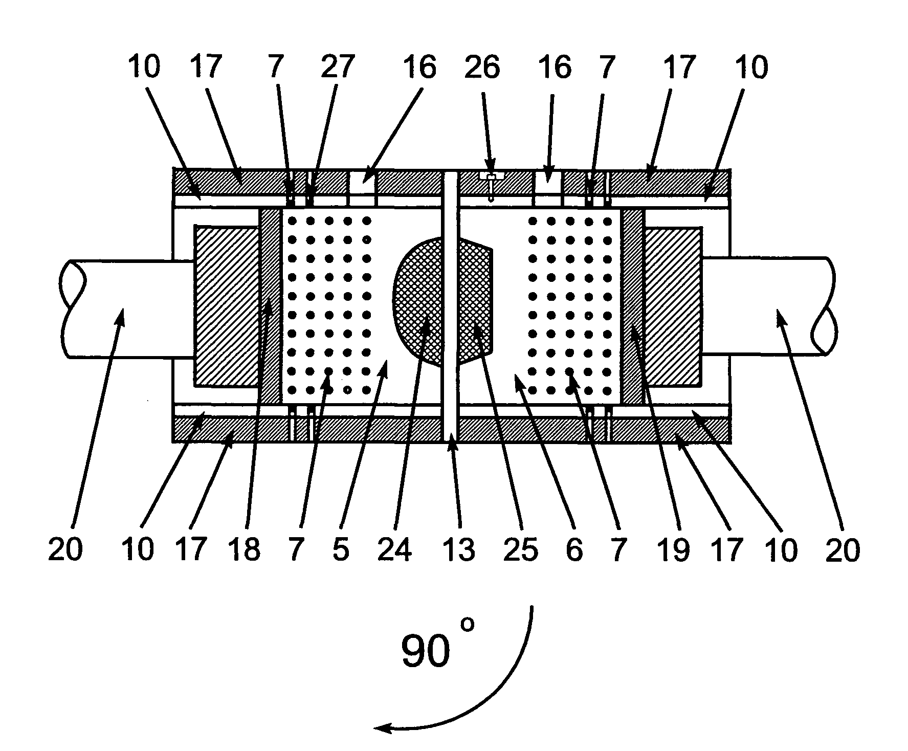
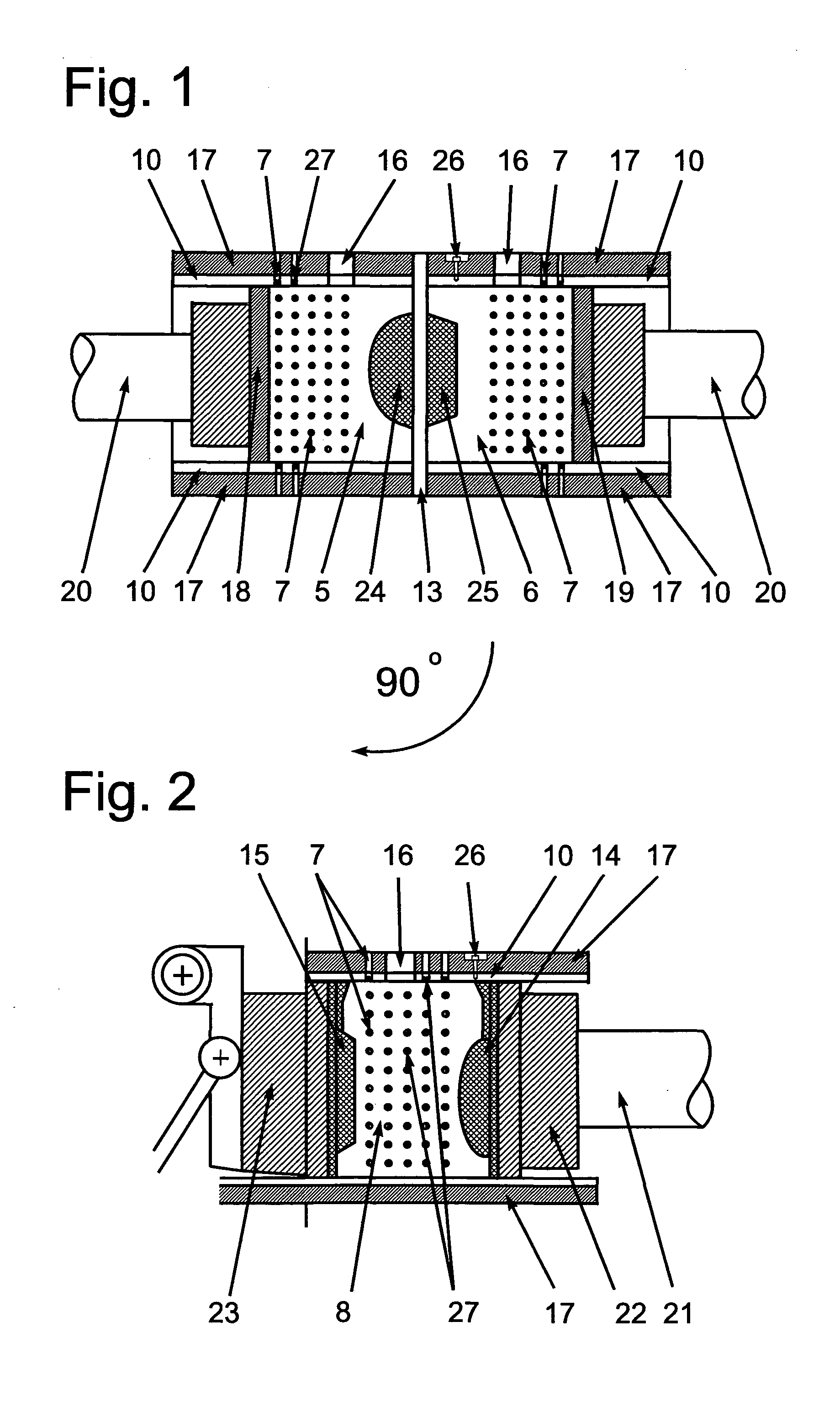
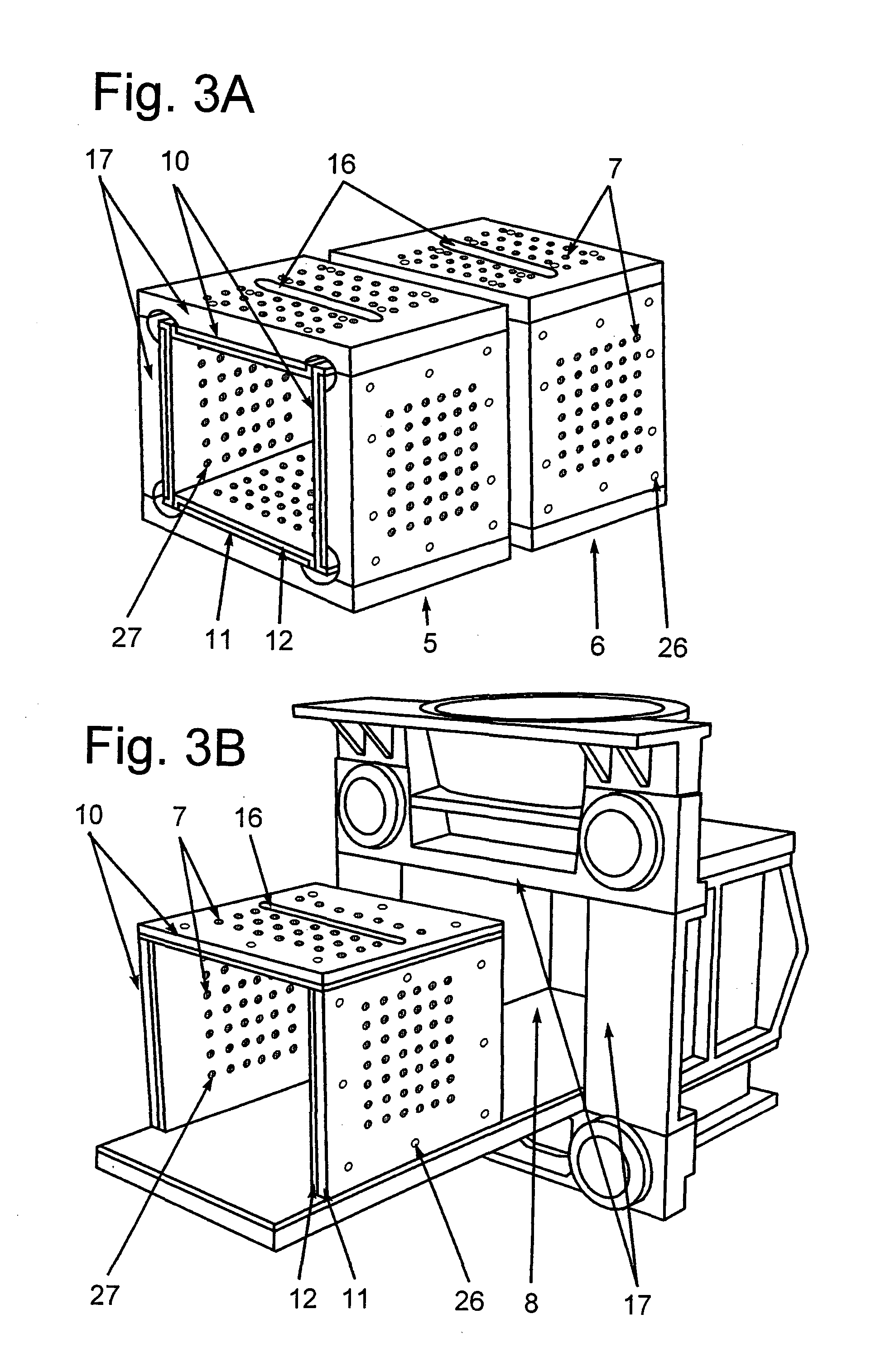
[0018]Sand moulds are often used in industrial casting of complex shaped metal products. Automatic machines or techniques for making sand moulds are known. Basically, most types of moulding machines comprise a sand filling and a squeezing section for the moulding of sand moulds. Two types of machines are shown in FIG. 1 and FIG. 2 and will be described in more details in the following.

[0019]In a moulding machine operating by the match-plate technique shown in FIG. 1, the sand filling and squeezing section comprises an upper and a lower moulding chamber 5 and 6, respectively, also known as a cope and drag flask fixed to and guided by a guiding and moving arrangement (not shown). By the activation of the guiding and moving arrangement, the moulding chambers may be moved in the direction towards each other or in a direction away from each other. A press arrangement 20 comprises an arrangement for moving the cope squeeze plate 18 and the drag squeeze plate 19 against each other and away...


PUM

PropertyMeasurementUnit
metallicaaaaaaaaaa
weightaaaaaaaaaa
thicknessaaaaaaaaaa

Abstract

The present invention relates to a lining plate (10) for lining a mould chamber in a sand moulding machine, said lining plate comprising a base unit (11), whereby said base plate may be equipped with functional openings for injection of particle material (16) and / or air exhaust (7) as well as fastening means for releasable fastening of the plate to the mould machine. A layer (12) of a synthetic resin material is adhered to said base unit (11). The layer (12) is intended to face the abrasive areas of said mould chamber, thereby forming part of the inner surface of the mould chamber. The invention further relates to a method of manufacturing a lining plate (10) for lining a mould chamber in a sand moulding machine comprising a base unit (11), said base unit (11) being equipped with functional openings for injection of particle material (16) and / or air exhaust openings (7) as well as fastening means for reliable fastening to the mould machine. A cover layer (12) of a synthetic resin material is adhered to said base unit (11). Moreover, the invention relates to a method of refurbishing a lining plate (10) for lining a mould chamber in a sand moulding machine comprising a base unit (11), said lining plate being equipped with functional openings for injection of particle material (16) and air exhaust openings (7) as well as fastening means for reliable fastening to the mould machine. A cover layer has been released from said unit (11) and a new cover layer of a synthetic resin material is being adhered to said base unit (11).

Description

FIELD OF INVENTION[0001]The present invention concerns a lining plate for lining a mould chamber in a sand moulding machine.PRIOR ART[0002]From EP 0 665 100 a sandwich construction composed of a base plate and a wearable part is known. The wearable part is a thinner ceramic or metallic layer adhered to a base plate by means of a polymeric woven adhesive material in order to compensate for variations in coefficient of expansion of the materials involved. Variations in expansion might lead to problems in tightness along borders, and the weight of this type of lining plate makes field replacement troublesome. Accordingly, when claiming high precision on thickness of the adhesive layer, joining three layers can cause intolerable variations in thickness of the complete plate.[0003]In U.S. Pat. No. 4,997,025 a wear plate is detachably fixated to a carrier plate by means of magnetic force and mechanical securing means. This type of fixation is however possible only for materials with magne...

Claims


Application Information

Patent Timeline
Patent Type & Authority Applications(United States)
IPC IPC(8): B28B7/36B29C33/40
CPCB22C11/02B22C19/00B22C15/00B22C11/10B29C39/10B29C39/123
Inventor HANSEN, TORBENJOERGENSEN, ALLANHANSEN, MOGENS
Owner DISA IND
Learn More