
Multiple interface device charger with removable battery pack

a multi-interface device and charger technology, applied in the direction of electrical appliances, electric vehicles, electrochemical generators, etc., can solve the problems of many chargers involving clumsy cables and ascetically unpleasing designs

Active Publication Date: 2011-12-06
VINCI BRANDS LLC
View PDF3 Cites 20 Cited by
  • Summary
  • Abstract
  • Description
  • Claims
  • Application Information

AI Technical Summary

Benefits of technology

"The present invention is a charging accessory for a portable electronic device that provides a convenient way to recharge the device's battery. The accessory includes a main charger body and a battery pack that can be easily connected together using a cable. The main charger body converts the power supply voltage to a suitable voltage for the device, while the battery pack provides the necessary power to recharge the device's battery. The accessory also includes power conditioning circuitry to adjust the voltage or current level of the power supply to the device's specific needs. The accessory can be used with both a 12-volt and 120-volt power supply. The battery pack includes a level display to indicate the charge level of the battery. The technical effects of this invention include convenient and easy charging of portable electronic devices, improved battery life, and compatibility with different power supply voltages."

Problems solved by technology

Unfortunately, these battery packs either use disposable batteries, or have rechargeable batteries that require a different charger than the portable device for which the battery pack is designed.
In addition, many chargers involve clumsy cables and ascetically unpleasing designs.

Method used


Image

  • Multiple interface device charger with removable battery pack
  • Multiple interface device charger with removable battery pack
  • Multiple interface device charger with removable battery pack

Examples


Embodiment Construction

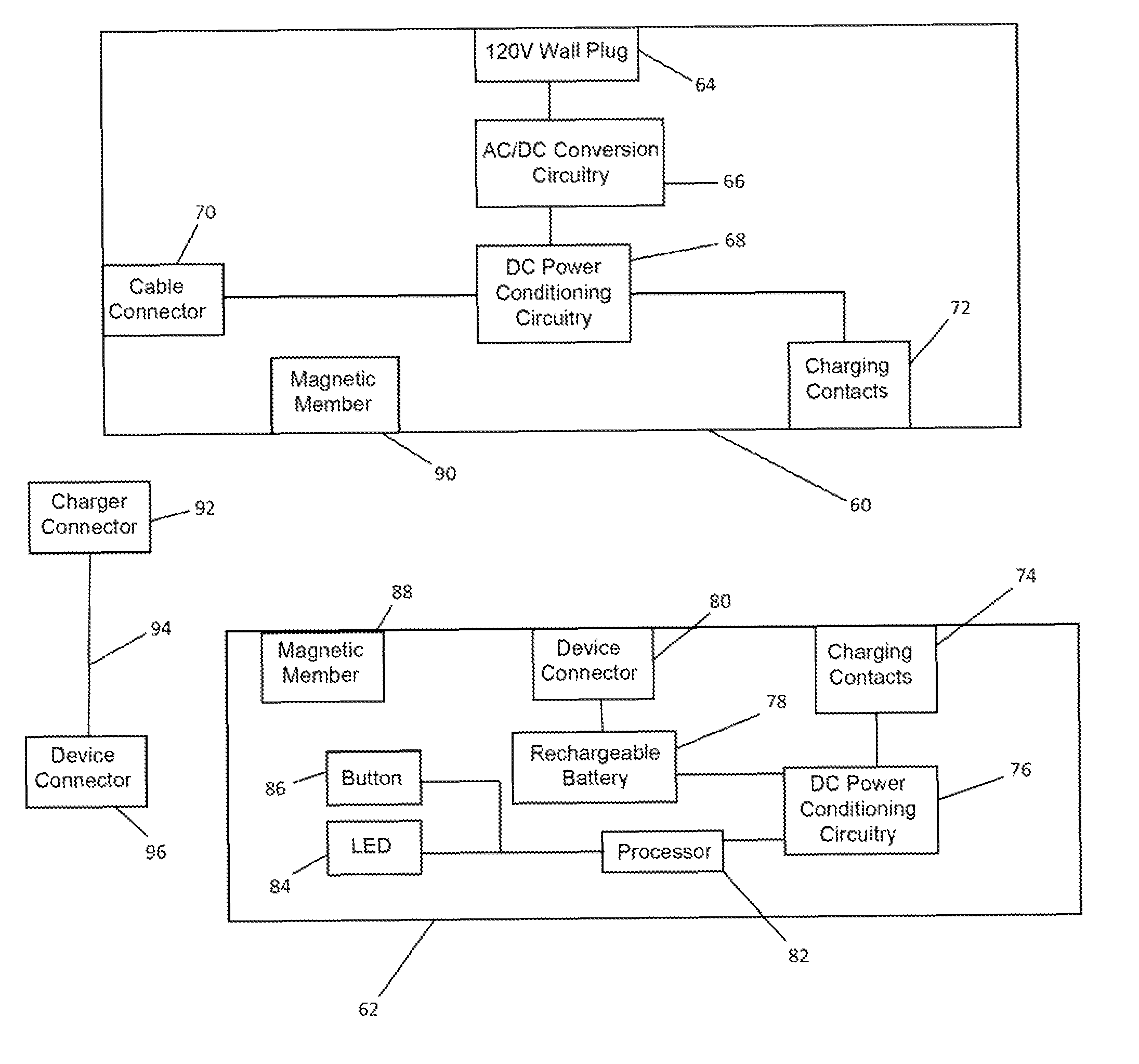
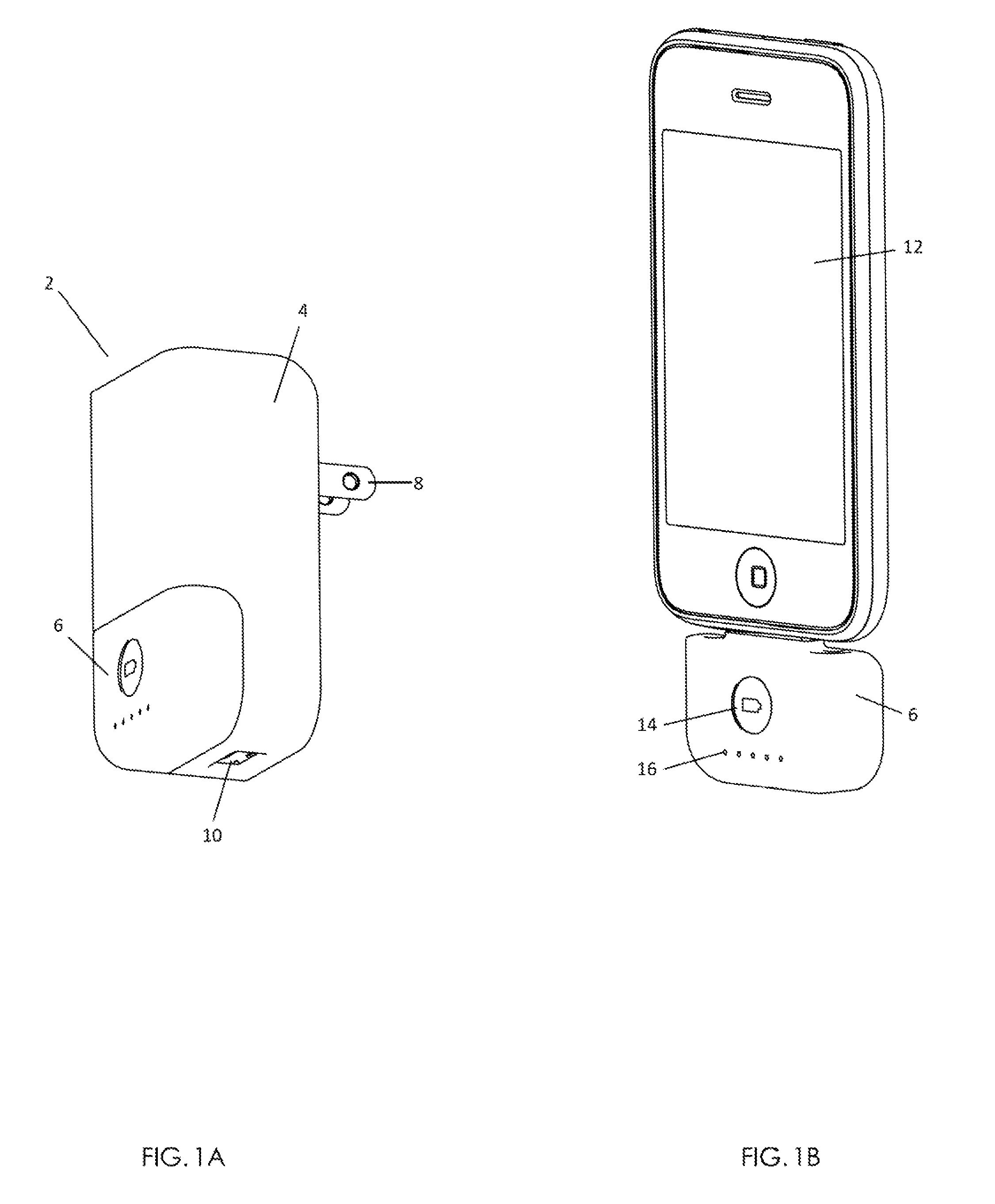
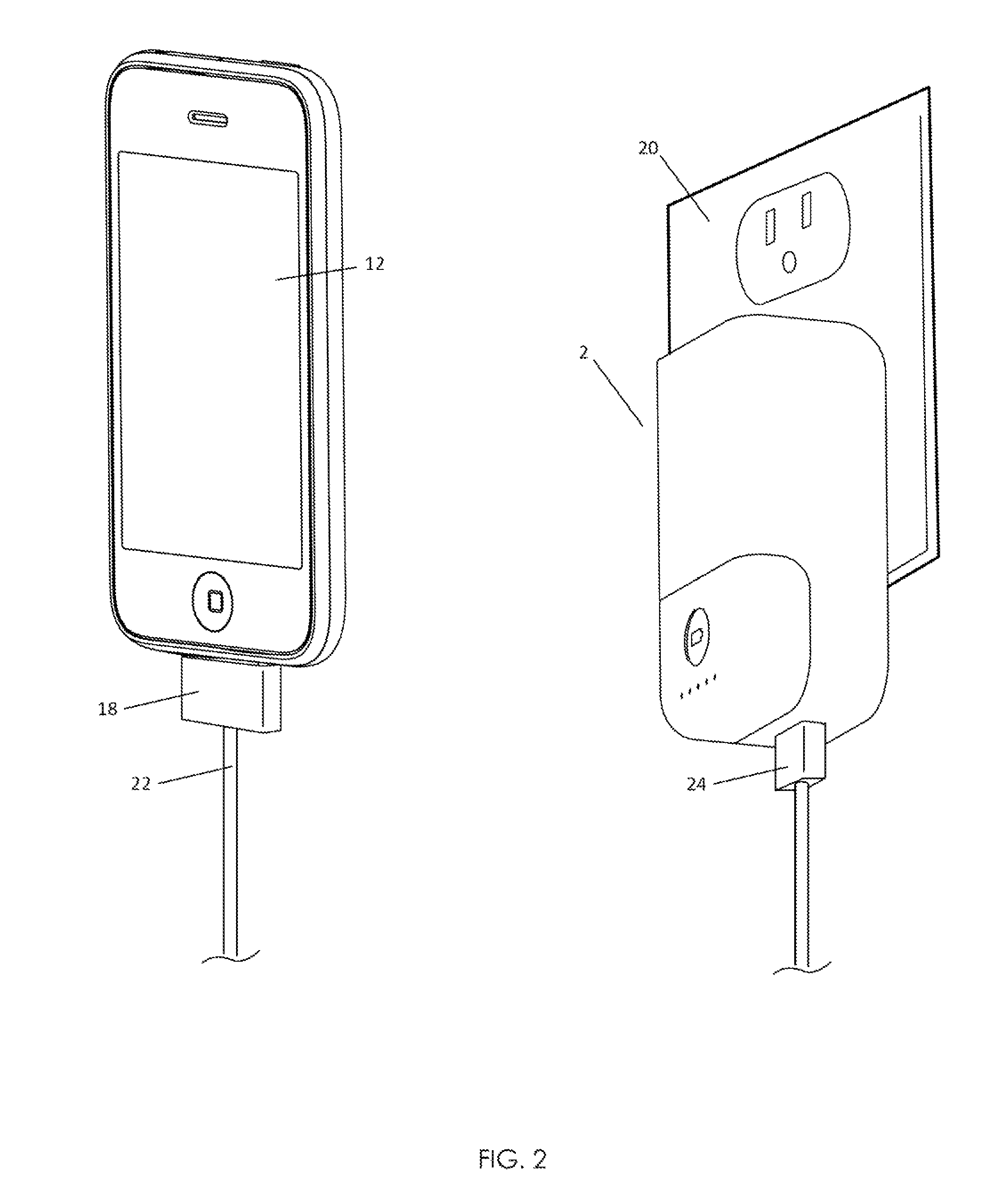
[0016]The present invention is an improved charger that provides a wireless backup power supply for a portable electronic device. Referring now to FIG. 1A, an illustration of a charging accessory constructed in accordance with an embodiment of the present invention is shown. The charging accessory 2 has a main charger body 4 and a removable battery pack 6 that electrically and physically couples to the main body portion 4. When coupled together, the housings of the main charger body 4 and the battery pack 6 form a unitary unit having an elongated cube shape. The main charger body 4 has standard wall outlet prongs 8 for coupling with a wall outlet and a cable connector 10. The cable connector 10 allows the main charger body 4 to be connected to a portable electronic device 12 such that the main charger body can charge the device as discussed in more detail below with respect to FIG. 2.

[0017]The removable battery pack 6 has a battery testing button 14 and battery level display 16. The...


PUM


Abstract

A charging accessory for a portable electronic device having a device input connector includes a main charger body portion having a power supply connection to an AC wall outlet that receives an AC power supply voltage. Power conversion circuitry converts the AC power supply voltage to a DC power supply voltage. A device connector is electrically coupled to the DC power supply voltage and configured to couple the DC power supply voltage to the device input connector of the portable electronic device. The main body also has a battery pack connector that is electrically coupled to the DC power supply voltage. The battery pack connector couples to a battery pack through a charging body connector that electrically connects to the battery pack connector and receives the DC power supply voltage when the battery pack is mounted on the main charger body portion. A rechargeable battery in the battery receives the DC power supply voltage to recharge the rechargeable battery. A device connector allows the battery pack to be directly coupled to the device input connector on the portable electronic device to provide an addition portable power supply for the device.

Description

CROSS-REFERENCES TO RELATED APPLICATIONS[0001]Not Applicable.STATEMENT REGARDING FEDERALLY SPONSORED RESEARCH OR DEVELOPMENT[0002]Not ApplicableREFERENCE TO SEQUENCE LISTING OR COMPUTER PROGRAM LISTING APPENDIX[0003]Not ApplicableBACKGROUND OF THE INVENTION[0004]Chargers for portable electronic devices are well known devices that condition power received from a power supply into the form needed by a particular device. These chargers typically have a voltage converter that converts an AC wall voltage into a DC voltage required to charge the device. Battery packs that can be coupled to a portable electronic device to charge the device when no connection to a wall outlet is available are also known. Unfortunately, these battery packs either use disposable batteries, or have rechargeable batteries that require a different charger than the portable device for which the battery pack is designed. In addition, many chargers involve clumsy cables and ascetically unpleasing designs.[0005]In l...

Claims


Application Information

Patent Timeline
Patent Type & Authority Patents(United States)
IPC IPC(8): H02J7/00
CPCH01M10/46H02J7/0054H02J7/0042H02J7/342Y02E60/10
Inventor GRIFFIN, JR., PAUL P.
Owner VINCI BRANDS LLC
Learn More