Image processing apparatus and image processing program for correcting image degradation

a technology of image processing and image degradation, applied in the field of image processing apparatus and image processing program, can solve the problems of not being able to properly restore the image signal input to the input portion b>101/b>, not being able to follow all of the actual camera shake, and not being able to detect, etc., and achieve the effect of excellent correction

Inactive Publication Date: 2011-12-06
GK BRIDGE 1
View PDF11 Cites 1 Cited by
  • Summary
  • Abstract
  • Description
  • Claims
  • Application Information

AI Technical Summary

Benefits of technology

[0023]It is an object of the present invention to solve the conventional problem described above and to provide an image processing apparatus and an image processing program that are impervious to frequency characteristics of a subject and can correct image degradation properly so as to restore an image.
[0027]In accordance with the present invention, it is possible to achieve an excellent effect of correcting image degradation properly so as to restore an image that is degraded due to camera shake, without being influenced considerably by the frequency characteristics of a subject.

Problems solved by technology

However, since the optical system is controlled in the optical camera shake correction system, such a digital camera has a larger body than that not having means for the optical camera shake correction.
Also, even when the optical camera shake correction is employed, it sometimes is impossible to follow all of the actual camera shake due to mechanical constraints.
In the former case, the camera shake amount can be detected for horizontal camera shake but cannot be detected for vertical camera shake due to its high image correlation.
As described above, the image processing apparatus disclosed in JP 11(1999)-284944A sometimes cannot detect the camera shake amount, leading to a problem that it is not possible to restore the image signal input to the input portion 101 properly.

Method used


Image

  • Image processing apparatus and image processing program for correcting image degradation
  • Image processing apparatus and image processing program for correcting image degradation
  • Image processing apparatus and image processing program for correcting image degradation

Examples


embodiment 1

1. Operation of Image Processing Apparatus

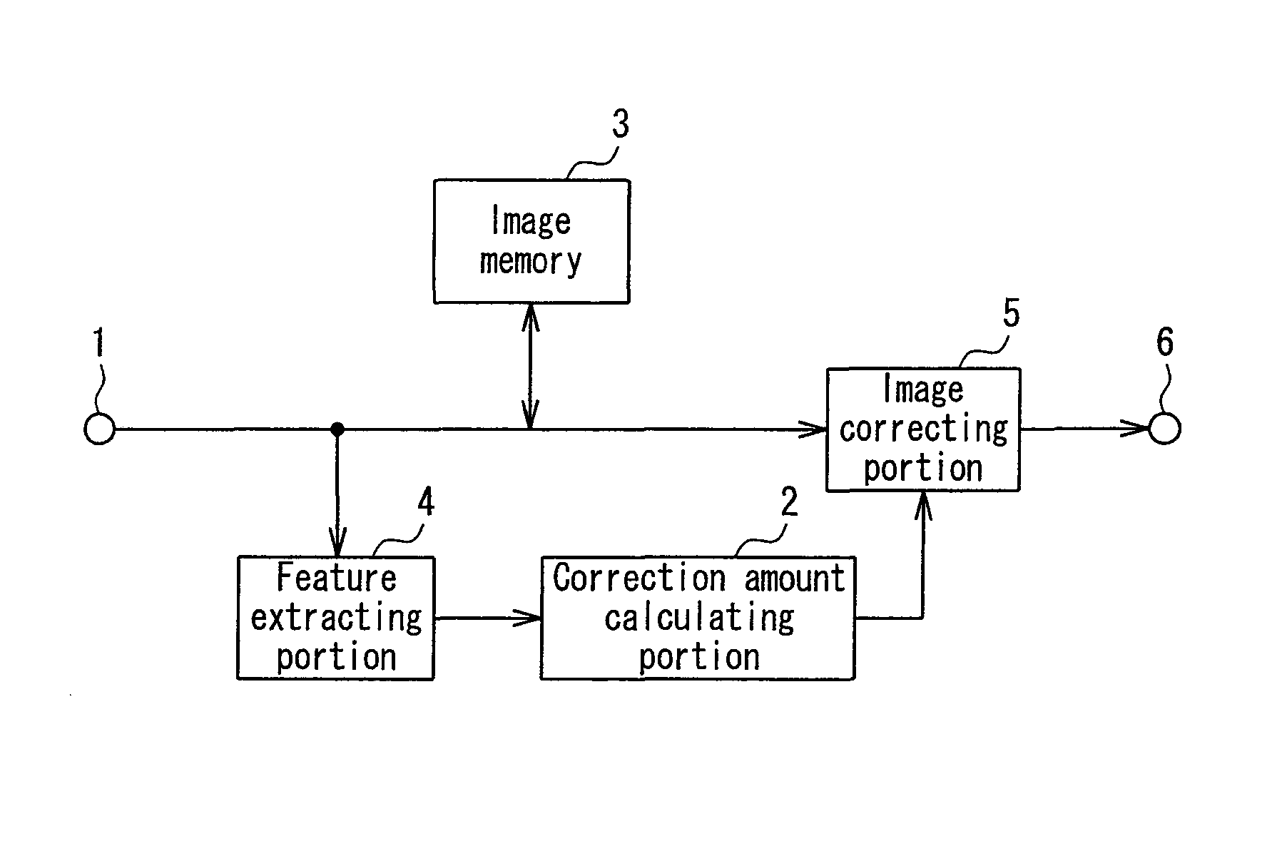
[0054]FIG. 3 is a block diagram showing a configuration of an image processing apparatus according to Embodiment 1. InFIG. 3, an image signal that is captured by a digital camera or the like and converted to digital form is input to an input portion 1. The image signal to be input to the input portion 1 may be an image signal that is obtained by capturing an image using a digital camera and recording it in a recording medium or an image signal that is obtained by scanning a photograph taken using a film camera and converting the data to digital form.

[0055]A feature extracting portion 4 extracts a feature of a frequency characteristic of the image signal input to the input portion 1. A specific extraction method will be described later. Based on the feature of the frequency characteristic extracted by the feature extracting portion 4, a correction amount calculating portion 2 calculates a correction amount of the frequency characteristic. An ...

embodiment 2

1. Operation of Image Processing Apparatus

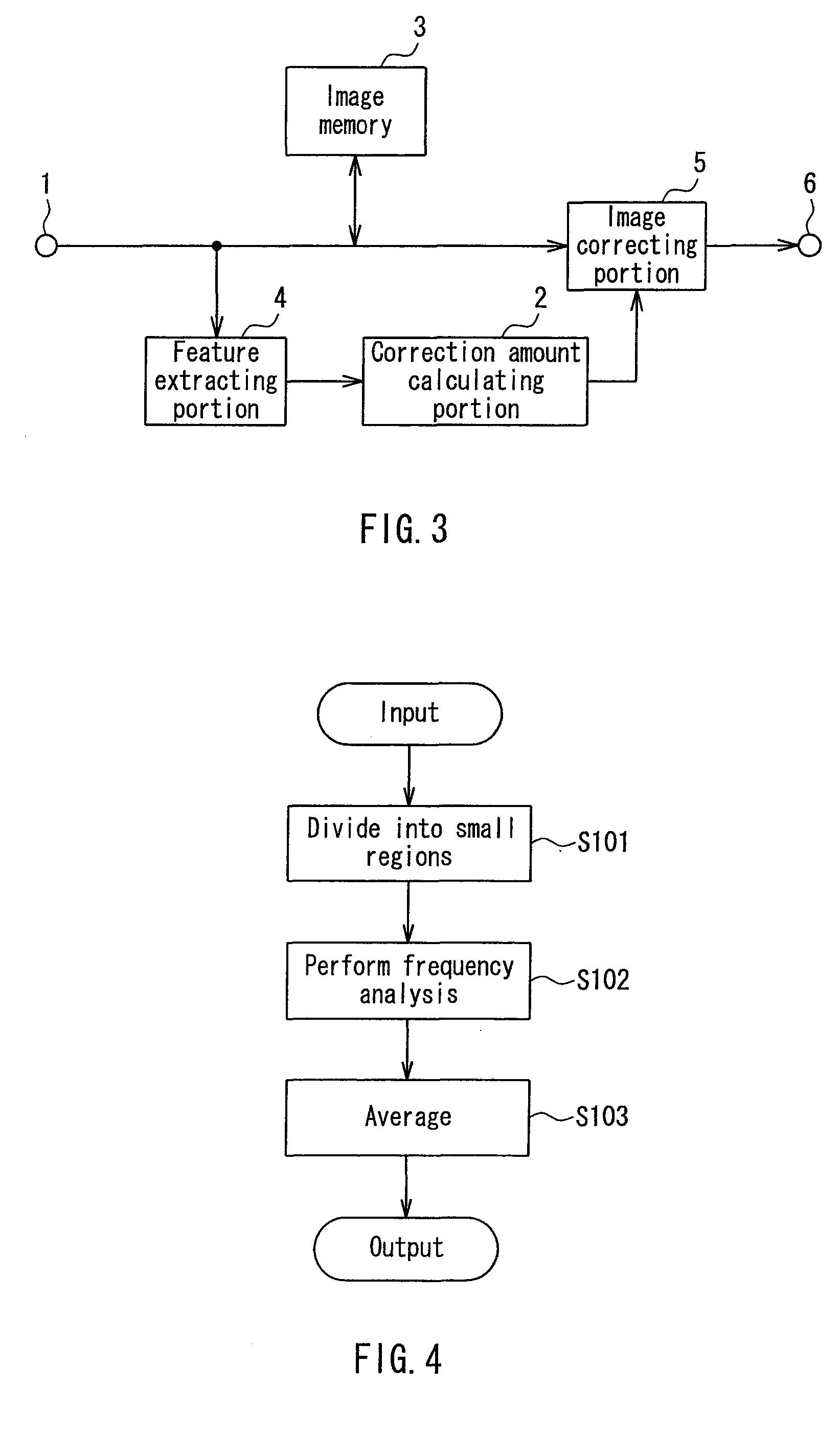
[0073]The feature extracting portion 4 in Embodiment 1 is capable of analyzing the frequency characteristics for the individual small regions in the image and averaging the frequency characteristics of the individual small regions over the entire screen. In contrast, the feature extracting portion 4 in Embodiment 2 is capable of analyzing the frequency characteristics for the individual small regions in the image and extracting maximum values over the entire screen based on the frequency characteristics of the individual small regions. The image processing according to Embodiment 2 makes it possible to extract accurately the degradation amount of the frequency characteristic due to camera shake in the image signal input to the image processing apparatus.

[0074]The configuration of the image processing apparatus according to Embodiment 2 is similar to that according to Embodiment 1, and thus, the detailed description thereof will be omitted. I...

embodiment 3

1. Configuration of Image Processing Apparatus

[0105]FIG. 17 shows a configuration of an imaging apparatus, which is an example of an image processing apparatus according to Embodiment 3. In FIG. 17, configurations similar to those in Embodiment 1 or 2 are given the same reference numerals, and the description thereof will be omitted. The image processing apparatus illustrated in Embodiment 3 is mounted in a digital camera.

[0106]A CCD image sensor 12 includes a large number of photoelectric conversion elements (pixels) in a matrix form, and converts an optical image that enters via a lens 11 into an electric image and outputs this electric image. Also, the CCD image sensor 12 is operable in a pixel mixing driving mode (a first driving mode) or an all-pixel readout mode (a second driving mode). The pixel mixing driving mode adds values of a plurality of pixels arranged horizontally and vertically and outputs the sum, and substantially thins out the pixels so as to give the output with...


PUM


Abstract

An image processing apparatus according to the present invention includes a feature extracting portion that extracts a feature of a frequency characteristic of an input image, a correction amount calculating portion that calculates a correction amount of the frequency characteristic from the feature extracted by the feature extracting portion, and an image correcting portion that corrects the input image according to the correction amount calculated by the correction amount calculating portion. This configuration achieves imperviousness to frequency characteristics of a subject and makes it possible to correct image degradation properly so as to restore an image.

Description

BACKGROUND OF THE INVENTION[0001]1. Field of the Invention[0002]The present invention relates to an image processing apparatus and an image processing program that are mounted in a digital camera or the like. In particular, the present invention relates to a technology for restoring an image that is blurred due to camera shake or the like.[0003]2. Description of Related Art[0004]In recent years, as digital cameras achieve a smaller size and a higher zooming factor, a camera shake correction has become necessary in many cases.[0005]The system of camera shake correction includes an optical camera shake correction system and an electronic camera shake correction system. In the optical camera shake correction system, an optical system is controlled according to the amount of camera shake, thereby keeping an image forming position constant on an imaging device. On the other hand, in the electronic camera shake correction system, at the time of signal processing of an image formed on an i...

Claims


Application Information

Patent Timeline
Patent Type & Authority Patents(United States)
IPC IPC(8): G06K9/40
CPCH04N1/4092H04N5/23248H04N5/23254H04N5/23267G06T5/003G06T2207/20021G06T2207/20052G06T2207/20201H04N23/68H04N23/6811H04N23/683
Inventor YAMAMOTO, YASUTOSHI
Owner GK BRIDGE 1
Why Eureka
Try Eureka