

Lane deviation prevention device
a technology of preventing devices and lane deviations, applied in vessel construction, steering initiations, instruments, etc., can solve problems such as driver discomfort with the amount of yaw moment applied, driver may be distracted or annoyed,
- Summary
- Abstract
- Description
- Claims
- Application Information
AI Technical Summary
Benefits of technology
Problems solved by technology
Method used
Image

Examples
second exemplary embodiment
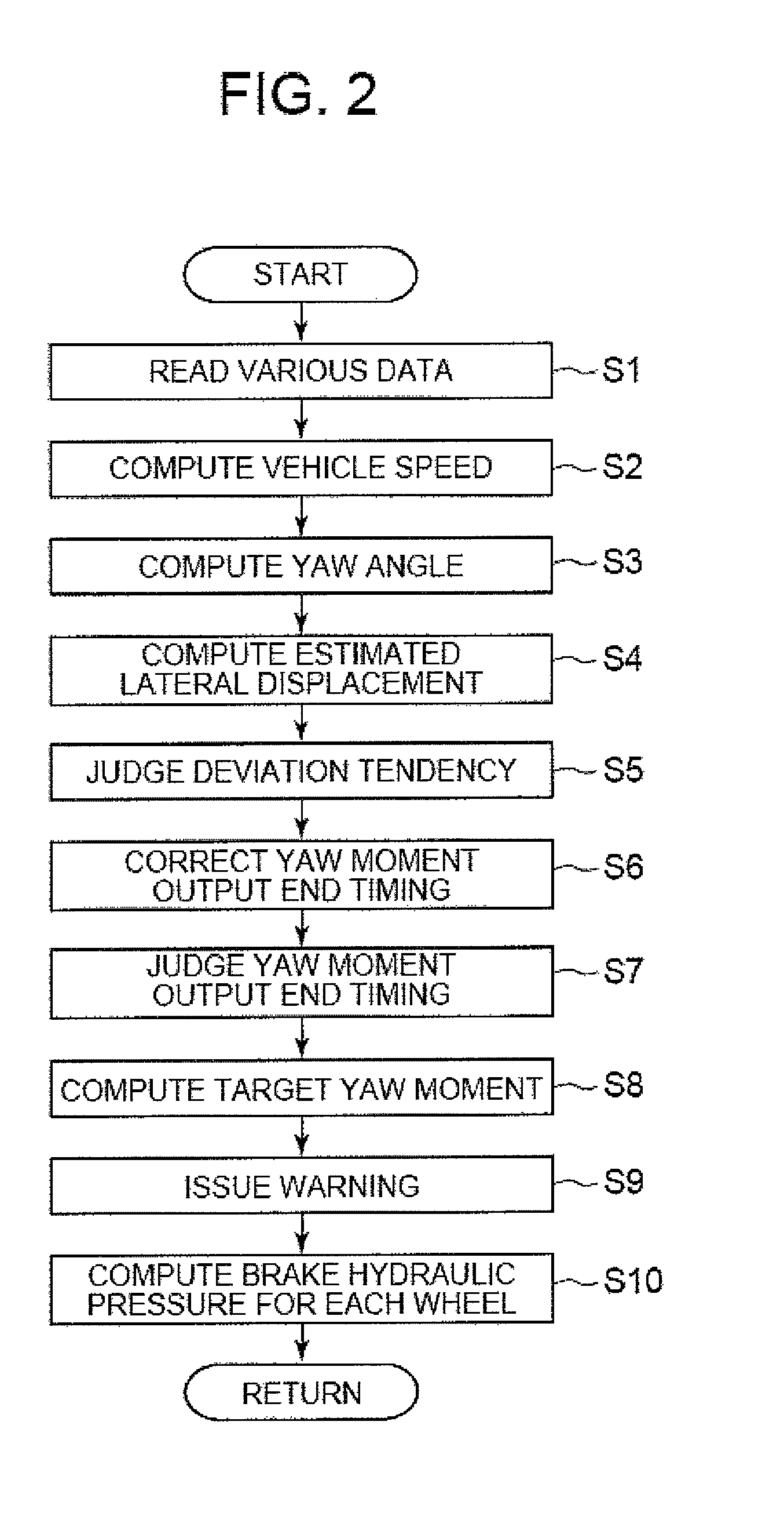
[0105]In the second exemplary embodiment, the arithmetic and logic operation processing performed in drive / braking force control unit 8 may be the same as that shown in FIG. 2, and the same processing procedure as that of the first exemplary embodiment may be performed, except that the method for correcting the yaw angles used for judging restriction on control in step S6 is different.
[0106]In particular, in selected embodiments, step S6, with the precondition that judgment of restriction of control for preventing deviation from the lane is performed by means of a unique yaw angle limit for control restriction judgment Ølim3 (hereinafter to be referred to as the third yaw angle limit for judgment of control restriction), said third yaw angle limit Ølim3 for control restriction judgment may be corrected based on the width of the lane of travel.
[0107]FIG. 7 is a diagram illustrating the relationship between the width of the lane of travel and third yaw angle limit Ølim3 for control re...
third exemplary embodiment
[0114]In the third exemplary embodiment, as with the first and second exemplary embodiments, the vehicle equipped with the lane deviation prevention device is a rear wheel drive vehicle.
[0115]In Embodiment 3, the arithmetic and logic operation processing procedure performed in drive / braking force control unit 8 may be the same as that shown in FIG. 2, and the same as that in the first and second exemplary embodiments, except that the method for correcting the yaw angle for control restriction judgment may be different in step S6.
[0116]That is, in the third exemplary embodiment, in step S6, the precondition may be that judgment of the timing of restricting control for preventing deviation from the lane may be performed by means of a unique yaw angle limit Ølim4 for control restriction judgment hereinafter to be referred to as the fourth yaw angle limit for control restriction judgment) Ølim4, and said fourth yaw angle limit Ølim4 for control restriction judgment may be corrected base...
fourth exemplary embodiment
[0123]In this embodiment, just as in the first three exemplary embodiments, the vehicle equipped with the lane deviation prevention device of the present disclosure may be a rear wheel drive vehicle.
[0124]In selected embodiments, the arithmetic and logic operation processing performed by drive / braking force control unit 8 may be the same as that shown in FIG. 2, that is, it is the same as the processing procedure in the first exemplary embodiment, except that the method for correcting the yaw angle for control restriction judgment in step S6 may be different.
[0125]That is, in step S6, just as in the first exemplary embodiment, the precondition may be that judgment of the timing of restriction of the control for preventing deviation from the lane is done by means of said first and second yaw angle limits Ølim1, Ølim2 for control restriction judgment, and said first and second yaw angle limits Ølim1, Ølim2 for control restriction judgment may be corrected taking into consideration of ...
PUM
 Abstract
Description
Claims
Application Information