
System and method for displaying and manipulating hierarchically linked data in a genealogy database using a graphical interface

a genealogy database and graphical interface technology, applied in the field of system and method for displaying and manipulating hierarchically linked data in a genealogy database using a graphical interface, can solve the problems of affecting the user's understanding of the databas

Inactive Publication Date: 2011-12-06
SHERWOOD ELECTRONICS LAB
View PDF7 Cites 8 Cited by
  • Summary
  • Abstract
  • Description
  • Claims
  • Application Information

AI Technical Summary

Benefits of technology

The EPD provides a clear and intuitive graphical interface for users to view, manipulate, and share genealogical data, overcoming the limitations of existing software by allowing seamless data management and import / export processes, reducing user effort and errors.

Problems solved by technology

Because these computer software programs use this limiting concept, it can be difficult to see relationships and lineages, manipulate data, add data into correct positions, see relationships and see different views of the data.
Present software programs are also limited in their ability to identify and display unlinked data in the database.
Once an individual is unlinked, the individual and the connected nodes “disappear” from the user's view and it is difficult for the user to see and understand what has been unlinked in the database.
One major problem in present genealogy programs is the data export selection process.
If a user wants to give part of his genealogy to a relative, he must go through a tedious selection process.
Likewise, when receiving information from someone else, importing that information into a user's database can cause horrendous problems and weeks of work to unravel the conflicts created by the import.

Method used


Image

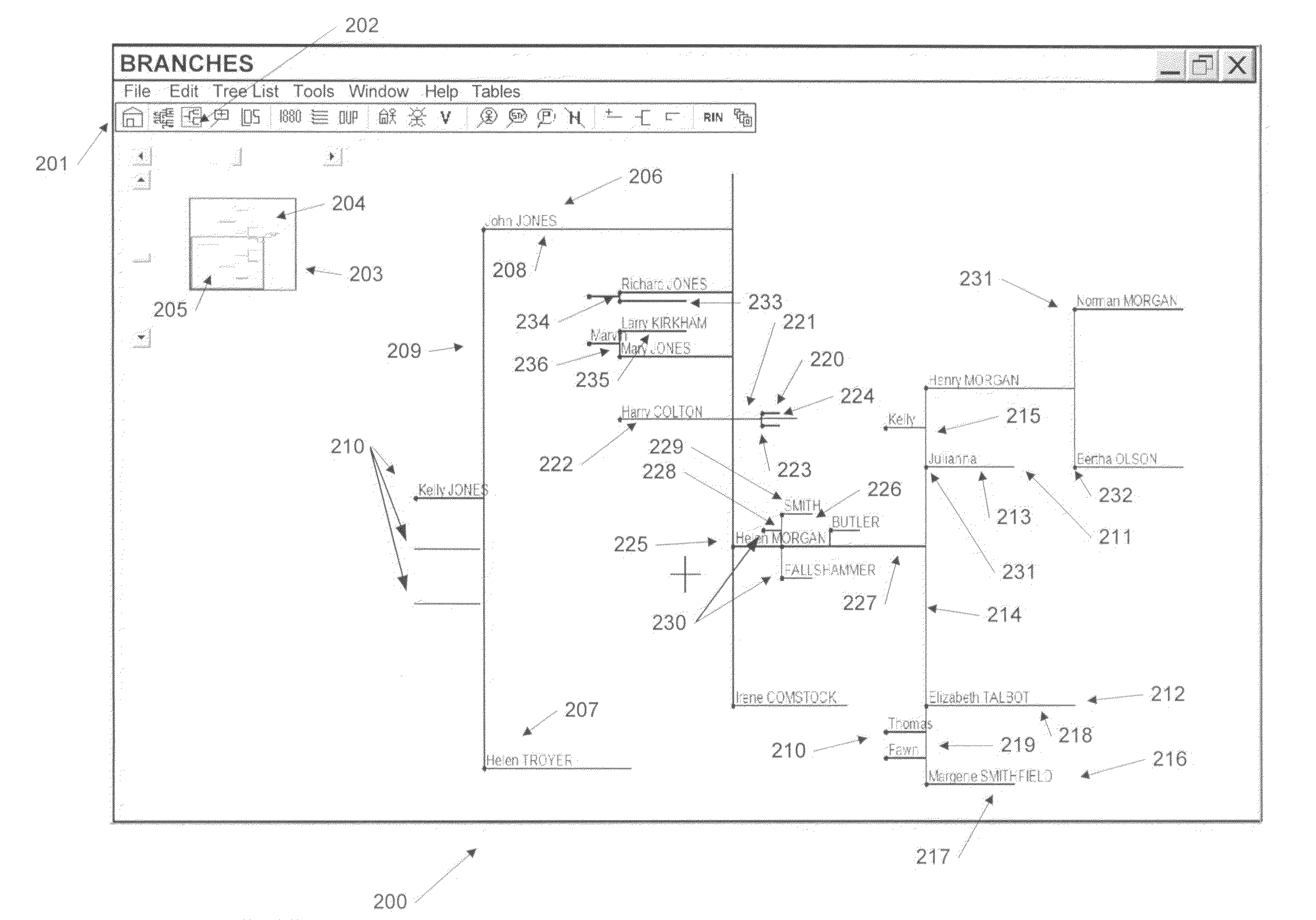
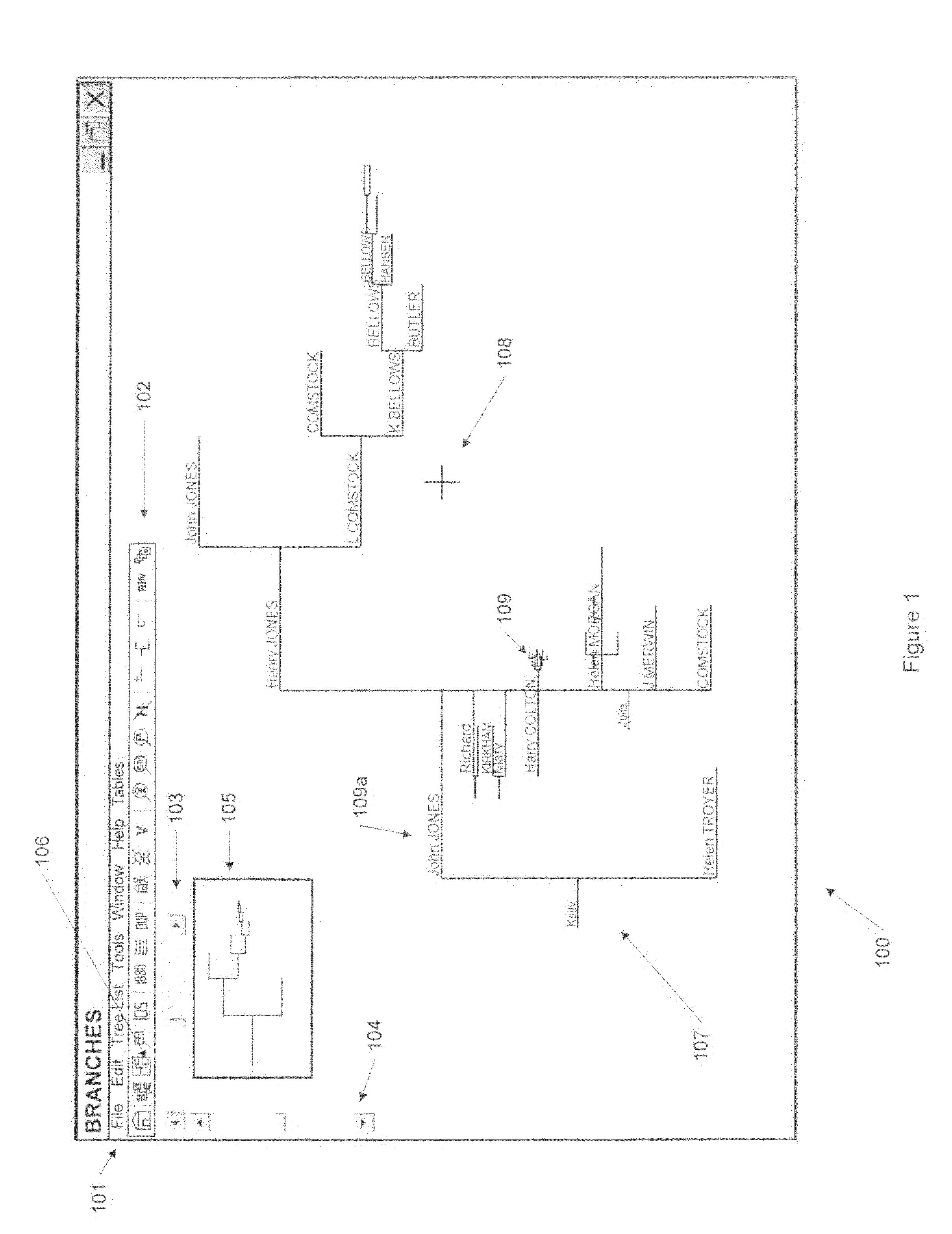
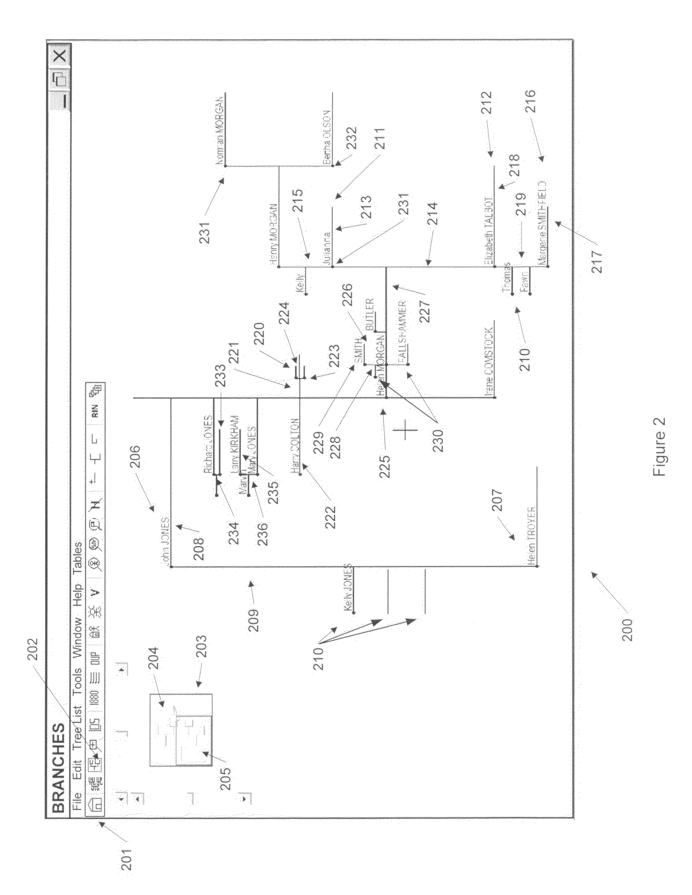
  • System and method for displaying and manipulating hierarchically linked data in a genealogy database using a graphical interface
  • System and method for displaying and manipulating hierarchically linked data in a genealogy database using a graphical interface
  • System and method for displaying and manipulating hierarchically linked data in a genealogy database using a graphical interface

Examples


Embodiment Construction

[0048]The presently preferred embodiments of the present invention will be best understood by reference to the drawings, wherein like parts are designated by like numerals throughout. It will be readily understood that the components of the present invention, as generally described and illustrated in the figures herein, could be arranged and designed in a wide variety of different configurations. Thus, the following more detailed description of the present embodiments, as represented in the Figures, is not intended to limit the scope of the invention, as claimed, but is merely representative of presently preferred embodiments of the invention.

[0049]The graphic program preferably operates on a conventionally known computer system (not shown). The computer system includes an internal memory for storing computer program instructions which control how a processing unit within the computer accesses, transforms and outputs data. The internal memory includes both a volatile and a non-volat...


PUM


Abstract

A system and method for displaying, searching, manipulating and modifying of hierarchically linked genealogy data in a relational database on a computer system. A graphic representation of the data in the database is displayed on a computer display device. The system uses zooming, a common function used in computer systems, to show more or less information in the database in readable form. Using the computer pointer devices, the data in the database can be manipulated, added, deleted, or moved. The system allows for changing of the root node individual thereby giving a different view of the database, to zoom in or zoom out and save that view of the database for future reference. The system displays all relationships of the data in the hierarchical structure by use of various sizes and type of lines and positions in the structure and shows for example data further away from the root node individual as a progressively smaller graphical image.

Description

CROSS-REFERENCED RELATED APPLICATIONS[0001]This application claims the benefit of U.S. Provisional Application No. 60 / 938,260, filed May 16, 2007, which application is incorporated herein by this reference.BACKGROUND OF THE INVENTION[0002]Genealogy or the gathering of family information concerning ancestors and descendants has become an extremely popular pastime. Searching out ancestor relationships and histories has spawned many industries, one of which is a prolific software community. Software is used to store and view family histories, relationships, individual data such as birth and death dates and places, religious affiliations and rites, personal histories etc.[0003]The genealogy software presently available uses the fundamental formats of a sheet called a “family group sheet” and a sheet called a “pedigree chart” for their basic display formats. Pedigree charts are used in many other areas including animal pedigrees and genetic pedigrees. Pedigrees are based on a common data...

Claims


Application Information

Patent Timeline
Patent Type & Authority Patents(United States)
IPC IPC(8): G06F3/00G06F17/00G06F9/00
CPCG06F17/30958G06F16/9024
Inventor SHERWOOD, JOHN H.MILLER, MICHAEL C.
Owner SHERWOOD ELECTRONICS LAB
Learn More