
Piercing member protection device

a protection device and piercing technology, applied in the direction of intravenous devices, infusion devices, infusion needles, etc., can solve the problems of staff being exposed to medical fluid, drug or solvent exposure risk, and particularly serious problems, so as to effectively prevent the user from accidental exposure, prevent the exposure of at least a piercing tip, and reduce the amount of accidents and incidents

Active Publication Date: 2011-12-13
CARMEL PHARMA
View PDF238 Cites 80 Cited by
  • Summary
  • Abstract
  • Description
  • Claims
  • Application Information

AI Technical Summary

Benefits of technology

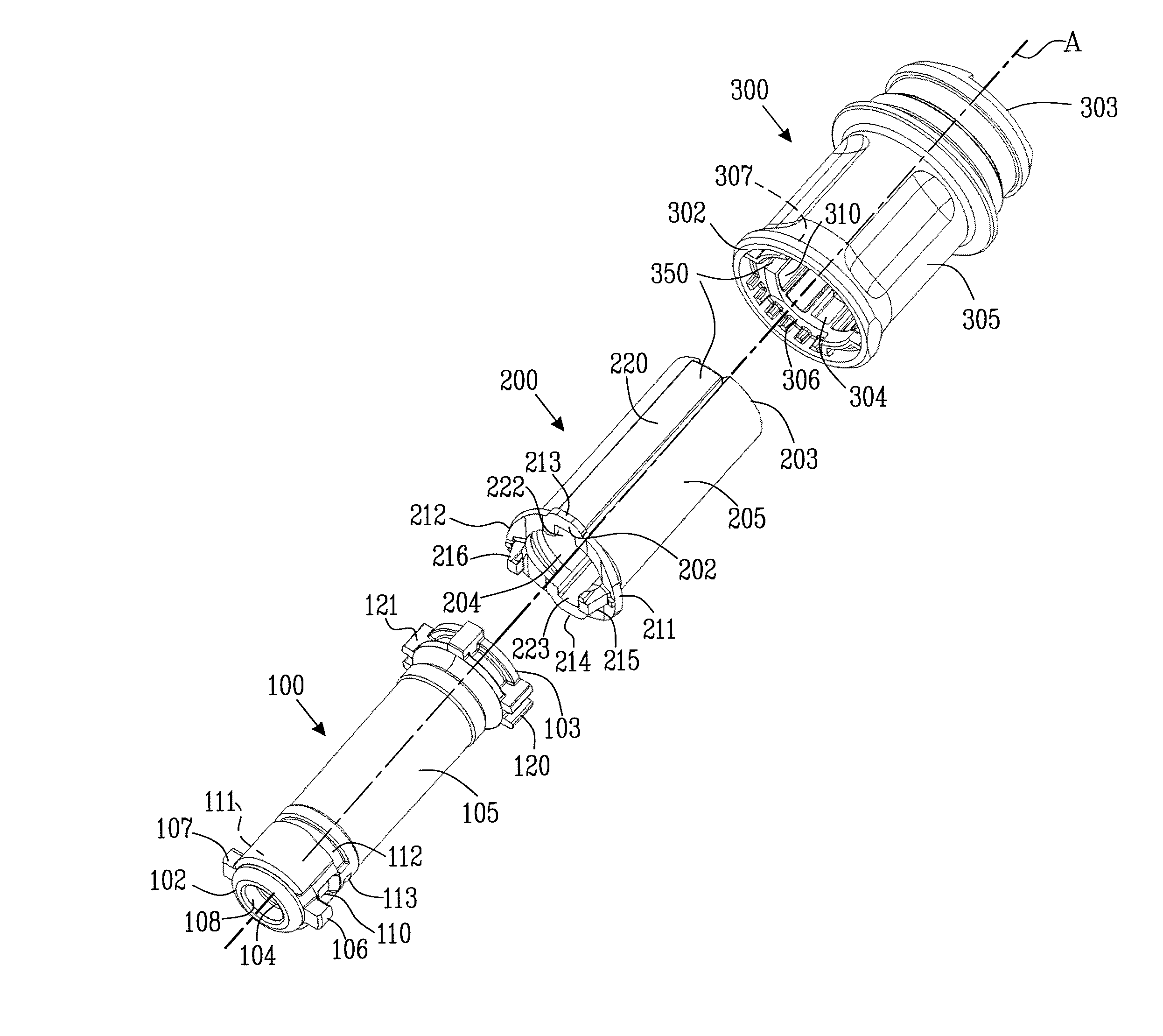
[0008]The piercing member protection device further comprises a first locking arrangement which comprises at least one deformable bias flange. The first locking arrangement has a locked position and an unlocked position, wherein when the first locking arrangement is in the locked position, the first cylindrical member is prevented from turning with respect to the second cylindrical member, and when the first locking arrangement is in the unlocked position, the first cylindrical member is permitted to turn with respect to the second cylindrical member. The locked position is altered to the unlocked position by deforming the deformable bias flange by bringing the piercing member protection device in contact with the first connection port. To change to the locked position, the piercing member protection device is removed from contact with the first connection port so as to permit the deformable bias flange to bias back from the deformation to the locked position; this functional relationship will be outlined in greater detail below. The piercing member protection device provides a safe system which prevents a user from accidentally exposing the piercing member before connecting it to a connection port due to the first locking arrangement.
[0012]Additionally or optionally, the at least one locking flange can comprise a proximal end, which is connected to the at least one deformable bias flange, and a distal end, intended to be engaged with at least one cavity, when the first locking arrangement is in the locked position. In this embodiment, the distal end of the at least one locking flange has at least one hook element to improve the engagement of the at least one locking flange, with the at least one cavity. The hook element can be arranged to improve the engagement with a cavity arranged in e.g. the first cylindrical member and with respect to the turning motion and as such, improve the locking capabilities of the first locking arrangement.
[0015]Furthermore, another aspect of the present invention relates to a piercing member protection device having a longitudinal centre axis A, the piercing member protection device comprises a first cylindrical member with a first and a second end, and an inner and outer surface. The first cylindrical member has a protection chamber for preventing the exposure of at least a piercing tip of a piercing member. The first cylindrical member further comprises a second cylindrical member, with a first and a second end and an inner and outer surface, wherein the first and second end, of the second cylindrical member is arranged between the first and second end, of the first cylindrical member. The first and second cylindrical members are at least partly encompassed by a third cylindrical member. The third cylindrical member comprises a piercing member comprising a piercing tip, and extends along the longitudinal centre axis A. The third cylindrical member is further movable along the longitudinal centre axis A so that the piercing tip of the piercing member can move between an exposed position, at which the piercing tip of the piercing member is exposed outside the protection chamber and an unexposed position, in which piercing tip of the piercing member is inside the protection chamber. The piercing member protection device further has a first and a second locking arrangement. The first locking arrangement is arranged to prevent the first cylindrical member from turning with respect to the second cylindrical member, and the second locking arrangement is arranged to prevent the third cylindrical member from movement long the longitudinal centre axis A. A piercing member protection device as described herein provides for a safe device which effectively prevents a user from accidental exposure to the piercing tip of the piercing member. This in turn reduces the amount of accidents and incidents which could possibly lead to injury.

Problems solved by technology

A serious problem in connection with drug preparation, drug administration and other similar handling is the risk that medical and pharmacological staff are exposed to drugs or solvents which might escape into the ambient air.
This problem is particularly serious when cytotoxins, antiviral drugs, antibiotics and radiopharmaceuticals are concerned.
In each of these steps staff may be exposed to the medical fluid by means of contamination.
The contaminations may contaminate the staff trough their lungs or vaporized medical fluid or aerosol in the air which condensates on the skin to thereafter penetrate the skin of the staff.
Some medicaments are even known to penetrate protection gloves and thereby contaminate the staff.
Exposure to contaminations like this may, on a long term basis, give rise to alarmingly high concentrations of medicaments in the blood or the human body of the just mentioned staff.
It has been understood that due to the many transferring steps between e.g. vials, syringes, infusion systems etc. the risk for contamination during the actual insertion and retraction of a needle from e.g. a vial has been underestimated and therefore not properly solved.
The device described in U.S. Pat. No. 4,576,211 is therefore not very user friendly since protection gloves may get caught between the teeth members and the slits during this rotational movement.
The devices mentioned above have a major drawback in terms of that they can be toggled between the first and the second position independently of whether the device is attached to a vial or not.
This has the implication that the needle may be exposed e.g. after blood transfusion has been made, or after the needle has been exposed to cytotoxins, and may thereby be a potential risk.

Method used


Image

  • Piercing member protection device
  • Piercing member protection device
  • Piercing member protection device

Examples


Embodiment Construction

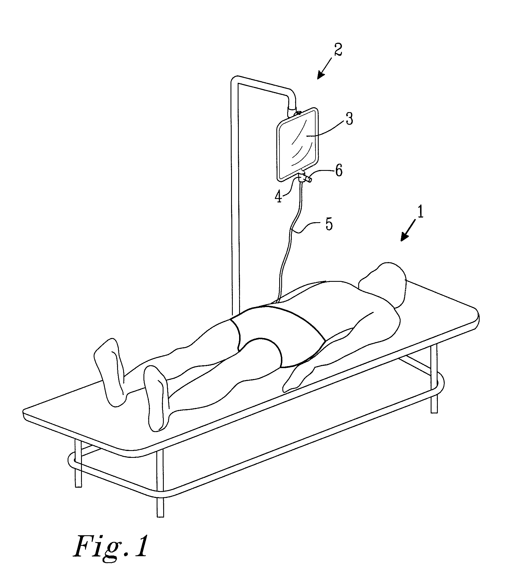
[0027]FIG. 1 shows a patient 1 that is being administrated with IV infusion from a medicament administration system 2 comprising a first fluid container 3 provided with a spike infusion device 4. The spike infusion device 4 comprises a fluid channel 5, in fluid communication with the blood circulation system of the patient 1, a piercing member (not shown), forced into the first fluid container 3, and a connection port 6, into which medicine can be administrated by means of a fluid injector device such as a syringe (not shown) connected to a piercing member protection device 9, comprising a piercing member.

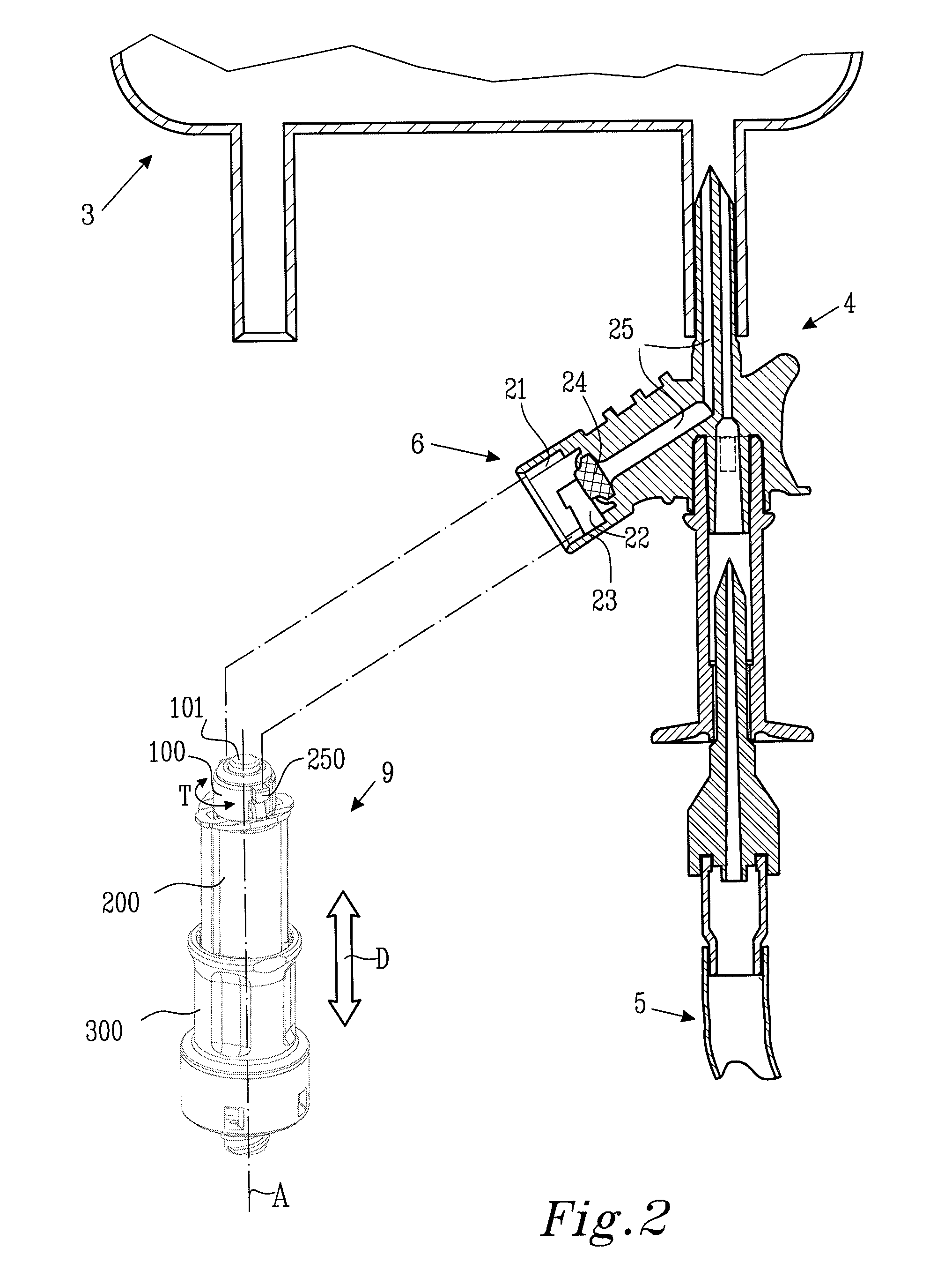
[0028]FIG. 2 shows partly a cross section of a spike infusion device and a connection port 6 to which the piercing member protection device 9 may be connected e.g. during drug administration to the first fluid container 3, although the drug administration to the first fluid container 3 is preferably done before said medicament administration system 2 is connected to a patient. The ...


PUM


Abstract

The present invention relates to a piercing member protection device (9) which comprises a first, a second and a third cylindrical member (100, 200, 300). The first cylindrical member (100) is at least partly encompassed by the second cylindrical member (200), and the second cylindrical member (200) is at least partly encompassed by the third cylindrical member (300). The third cylindrical member (300) comprises a piercing member (400) having a piercing tip (401). A first locking arrangement (250) is arranged to enable or prevent the turning of the first and third cylindrical member, with respect to the second cylindrical member, while a second locking arrangement (350) is arranged to enable or prevent movement of the piercing member (400) along the longitudinal center axis A, so as to expose the piercing tip (401) of the piercing member (400). The piercing member protection device (9) provides a safe device which reduces the risk of accidental exposure of the piercing tip (401) and contamination for a user.

Description

TECHNICAL FIELD[0001]The present invention relates to a piercing member protection device which comprises a locking arrangement with a deformable bias flange, to prevent the turning of a first cylindrical member with respect to a second cylindrical member, the locking arrangement is altered between a locked position and an unlocked position by deforming the deformable bias flange.BACKGROUND OF THE INVENTION[0002]A serious problem in connection with drug preparation, drug administration and other similar handling is the risk that medical and pharmacological staff are exposed to drugs or solvents which might escape into the ambient air. This problem is particularly serious when cytotoxins, antiviral drugs, antibiotics and radiopharmaceuticals are concerned. Other hazardous areas may be sample taking, such as samples concerning virus infections or the like. When performing infusions, it is often necessary to inject a drug or other medical substance into the infusion fluid inside an inf...

Claims


Application Information

Patent Timeline
Patent Type & Authority Patents(United States)
IPC IPC(8): A61M25/16A61M5/32
CPCA61M5/1626
Inventor NORD, LARSHORPPU, PETRI
Owner CARMEL PHARMA
Learn More