
Rotor having embedded permanent magnet

a permanent magnet and rotating shaft technology, applied in the direction of magnetic circuit rotating parts, dynamo-electric machines, magnetic circuit shape/form/construction, etc., can solve the problems of inability to suitably obtain conventional v or u-shaped arrangement of permanent magnets, and difficulty in compactness, so as to reduce the amount of permanent magnets

Active Publication Date: 2011-12-13
HYUNDAI MOTOR CO LTD +2
View PDF15 Cites 4 Cited by
  • Summary
  • Abstract
  • Description
  • Claims
  • Application Information

AI Technical Summary

Benefits of technology

[0011]In one aspect, the present invention is directed to a rotor for a hybrid car, particularly where the preferred structure of arranging a permanent magnet suitable for a rotor core having a thin, circular, hollow section and a preferred structure that reduces the amount of the permanent magnet.
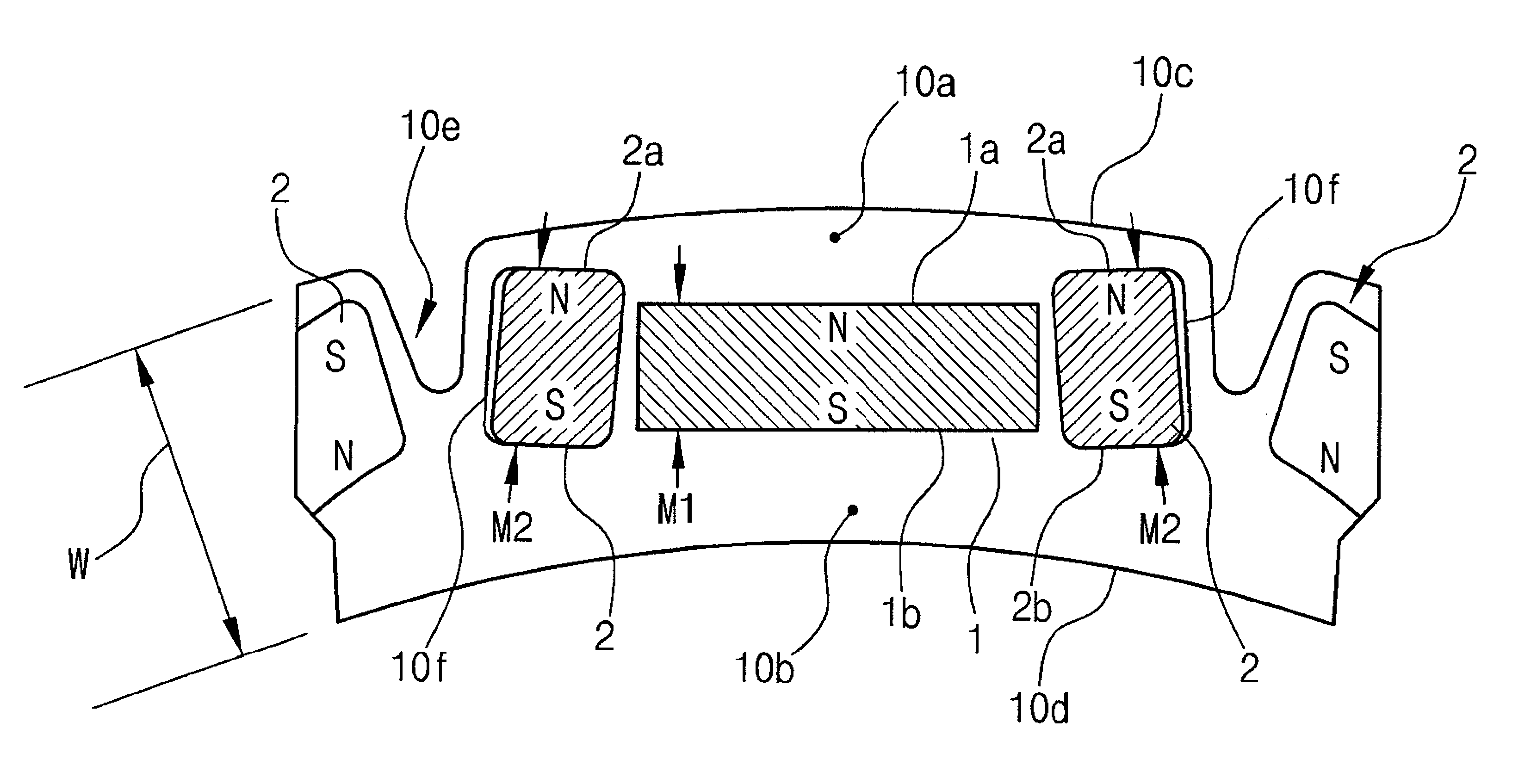
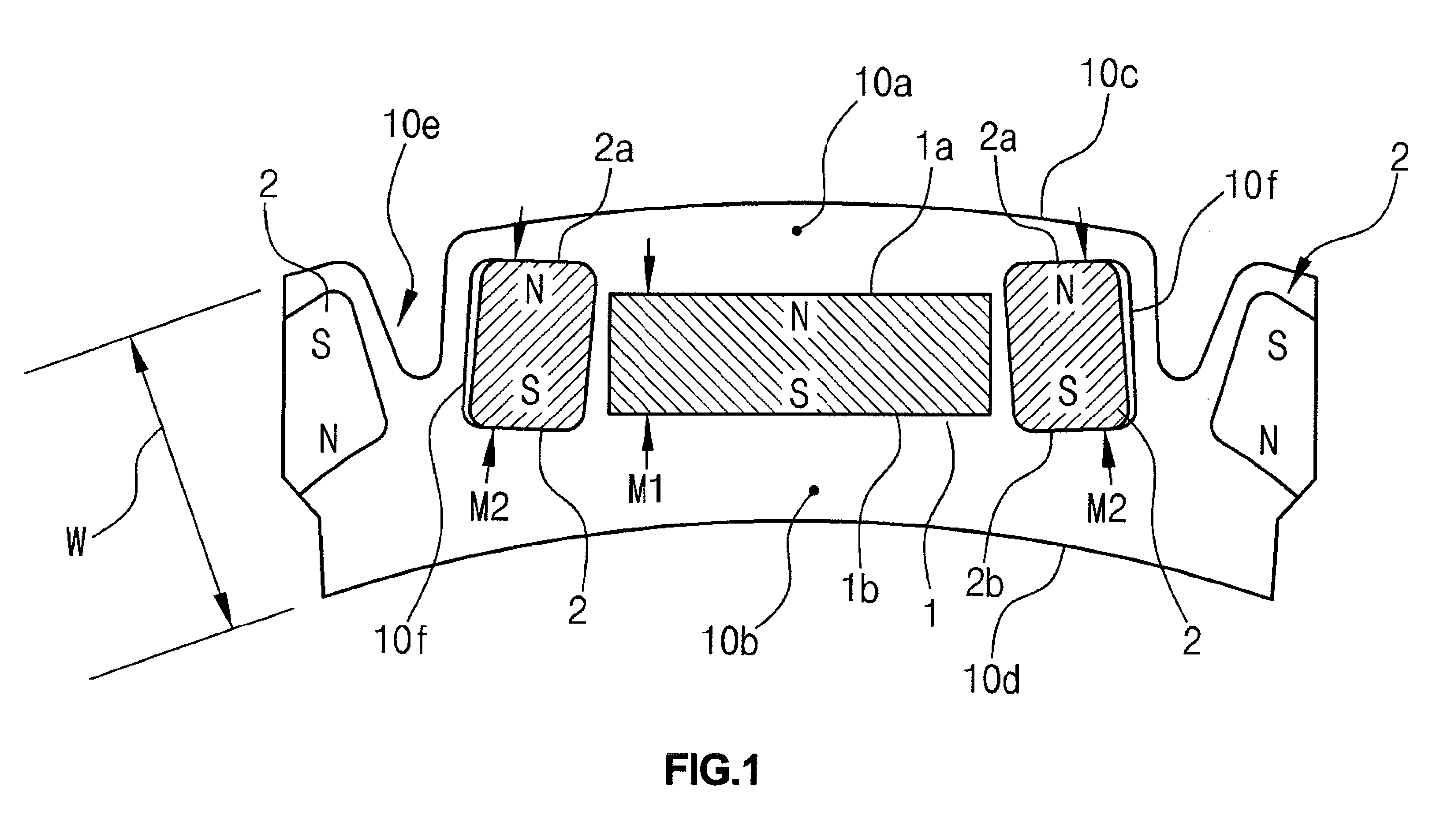
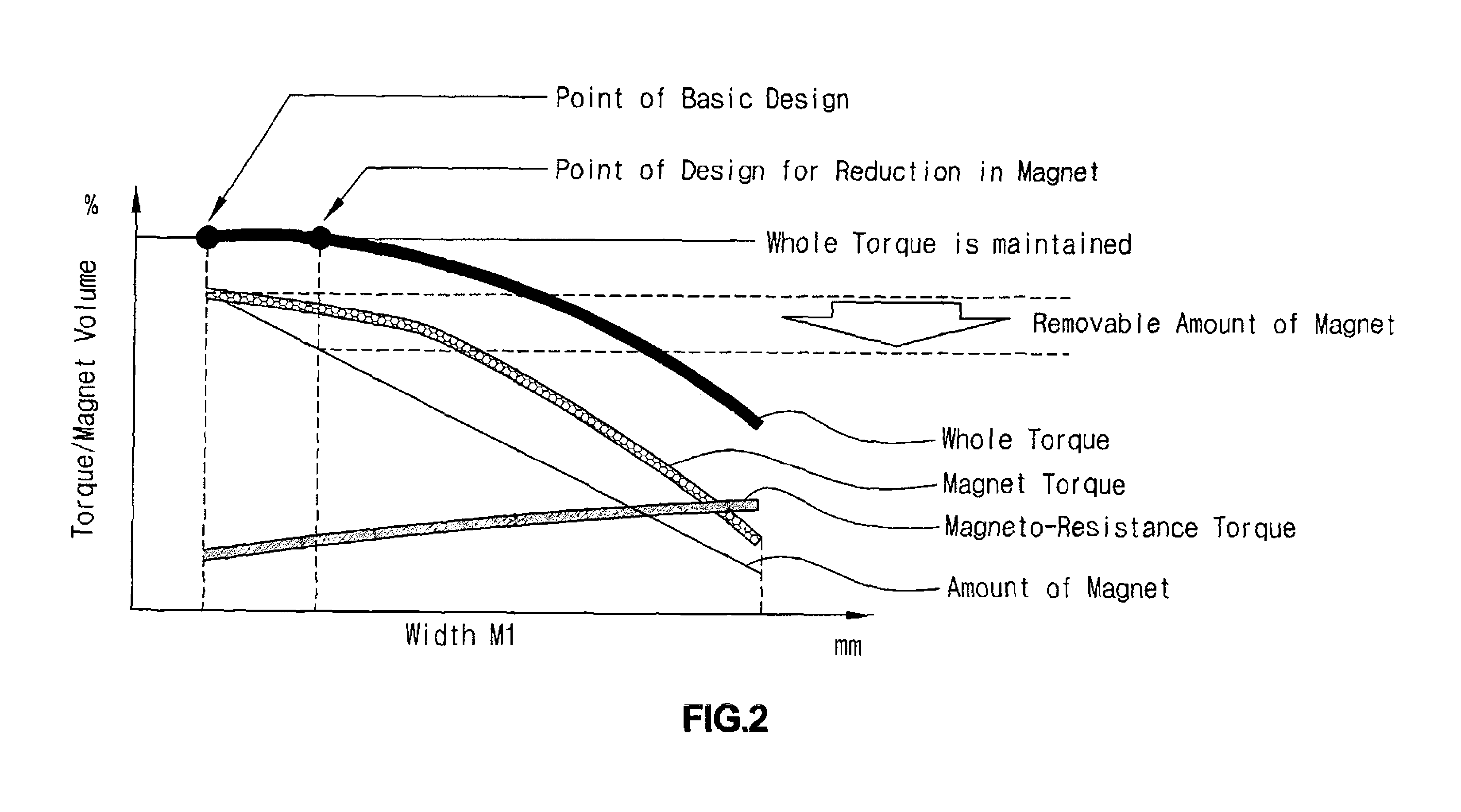
[0015]In other further embodiments, according to the magnet-embedded rotor of the present invention, the width between the magnetic poles of the center magnet is made suitably less than that of the side magnets, accordingly reducing the amount of magnet used. Accordingly, the reduction in width of the center magnet allows the volume of the pole-front side core from the outer circumference of the rotor core to the polar surface of the center magnet to increase, which causes magneto-resistance torque to suitably increase, thereby maintaining the torque while reducing the amount of magnet. In further embodiments, the output characteristic can be maintained, the amount of the magnets used can be reduced by about 12% as compared to that of the prior art, and thus the manufacturing cost can be reduced. In certain preferred embodiments, the center magnet and the side magnets are preferably embedded in a substantially linear form in the rotor core parallel with the tangential line of the outer circumference thereof, so that a multi-pole and high torque motor can be suitably realized using the rotor core even having the circular, thin section with a large hollow center portion.
[0016]In further embodiments, owing to the arrangement in which the respective polar surfaces of the side magnets are suitably inclined towards the center magnet, magnetic fluxes from an electromagnet (stator coil) can smoothly pass through the pole-front side core from the outer circumference of the rotor core to the polar surface of the center magnet without being blocked by the side magnets, thereby suitably enabling the magneto-resistance torque in the pole-front side core to be considerably increased.
[0017]In further embodiments, owing to the arrangement in which the polar surface of the center magnet towards an inner circumference of the rotor core is at least aligned with a line connecting those of the side magnets towards the inner circumference, or is arranged towards the outer circumference of the rotor core, because of the center magnet, the magnetic permeability of the pole-rear side core from the inner circumference of the rotor core to the rear-side polar surface of the center magnet is not blocked so that a magnetic path through the pole-rear side core is suitably secured and the magnetic fluxes are not saturated in the magnet, resulting in suitably maintaining the output of a motor even though the amount of center magnet used has been reduced.
[0018]According to further embodiments, owing to the preferred arrangement in which the center magnet is a permanent magnet having a smaller coercive force than the side magnets and suitably composed of a lower amount of rare metal than the side magnets, the cost of the magnet and therefore the motor can be suitably reduced. In addition, because the amount of a reverse magnetic field applied onto the pole center portion is suitably small, it is not necessary to maintain high magnetic force in the pole center portion, and there is no effect on the output characteristics of a motor.

Problems solved by technology

IPM motors as described in the art can obtain suitably high torque owing to a substantially U-shaped arrangement of the magnets, but the diameter of the rotor needs to be suitably increased making it difficult to make them compact.
Accordingly, the rotor core thereof has a circular hollow section with the center being largely empty and thus a conventional V or U shaped arrangement of permanent magnets cannot be suitably obtained.
Further, since a rare metal such as niobium as a high coercive magnet is expensive, in order to reduce costs, a structure for reducing the amount of magnets to be used is also required.

Method used


Image

  • Rotor having embedded permanent magnet
  • Rotor having embedded permanent magnet
  • Rotor having embedded permanent magnet

Examples


Embodiment Construction

[0027]As described herein, the present invention includes a magnet-embedded rotor in a motor comprising planar permanent magnets, wherein the magnets are circumferentially arranged at regular intervals in a cylindrical rotor core, and wherein electrolytic galvanized iron plates are laminated on one another.

[0028]In one embodiment, the outer circumferential surfaces of the permanent magnets are arranged so as to become alternating poles of N and S.

[0029]In one embodiment, the permanent magnets further comprise a 3-part arrangement including a center magnet and two side magnets.

[0030]In another embodiment, the width of a polar surface of each side magnet is smaller than that of the center magnet.

[0031]In another further embodiments, the magnets are embedded in the rotor core so as to be parallel with a tangential line thereof, and a width between both poles of the center magnet is smaller than those of the side magnets, and a volume of the pole-front side core from an outer circumfere...


PUM


Abstract

A structure for arranging a permanent magnet suitable for a rotor core having a thin, circular, hollow ring section and a structure for reducing the amount of the permanent magnet are provided.

Description

CROSS-REFERENCE TO RELATED APPLICATION[0001]This application claims the benefit of Japanese Patent Application No. 2009-053240, filed on Mar. 6, 2009, the entire disclosure of which is hereby incorporated by reference.BACKGROUND OF THE INVENTION[0002]1. Field of the Invention[0003]The present invention relates, in general, to a rotor having an embedded permanent magnet, and more particularly, to a structure comprising a permanent magnet suitable for a rotor core preferably having a thin, circular, hollow section and a structure which suitably reduces the amount of permanent magnet.[0004]2. Description of the Related Art[0005]Generally, a synchronous motor using a permanent magnet (or a magnet) preferably includes a surface permanent magnet (SPM) type motor in which a permanent magnet is suitably attached onto the surface of a rotor, and an interior permanent magnet (IPM) type motor in which a permanent magnet is suitably embedded into a core of a rotor. The IPM type motor is general...

Claims


Application Information

Patent Timeline
Patent Type & Authority Patents(United States)
IPC IPC(8): H02K21/12
CPCH02K1/2766H02K1/28H02K1/27
Inventor HIROSHI, NISHIMURA
Owner HYUNDAI MOTOR CO LTD
Learn More