Air conditioning apparatus for vehicle

a technology for air conditioning apparatus and vehicle, which is applied in the direction of lighting and heating apparatus, machine operation mode, domestic stoves or ranges, etc., can solve the problems of difficulty in maintaining the volume of air, so as to achieve the effect of increasing the volume of air conducted in each duct and not increasing the overall size of the air conditioning apparatus

Active Publication Date: 2011-12-20
DENSO CORP
View PDF9 Cites 10 Cited by
  • Summary
  • Abstract
  • Description
  • Claims
  • Application Information

AI Technical Summary

Benefits of technology

[0007]The present invention is made in view of the foregoing matter, and it is an object of the present invention to provide an air conditioning apparatus for a vehicle, having a structure that is capable of increasing the volume of air blown from an opening of a side wall of a unit case without increasing an overall size of the air conditioning apparatus.
[0009]In the above construction, the tubular part is disposed between the fan casing and the end of the second heat exchanger, the hollow space of the tubular part is in communication with the space provided downstream of the second heat exchanger through the communication portion. Thus, in addition to the air blown from the side opening, the air passing through the communication portion can be blown from the passage opening through the hollow space. As such, the volume of air blown from the side opening and the passage opening is increased. Since the door is configured such that the side opening and the communication portion are opened and closed simultaneously to each other. Therefore, it is less likely that the overall size of the air conditioning apparatus will be increased.
[0010]Further, since the tubular part is disposed between the fan casing and the end of the second heat exchanger, it is less likely that the air inside of the fan casing will be affected by heat of the second heat exchanger. Also, because the air inside of the hollow space is blown out from the passage opening, air conditioning efficiency improves.
[0012]The communication portion is provided by the tubular part, and the communication portion is opened and closed by the door, simultaneously with the opening and closing of the side opening. The air passing through the side opening and the passage opening are conducted into each of the first and second duct. Accordingly, the volume of air conducted in each duct is increased, without increasing an overall size of the air conditioning apparatus.

Problems solved by technology

However, in an air conditioning case having foot openings simply on side walls, because a flow direction of air is largely changed while the air flowing into the foot openings, it is difficult to maintain the volume of air.
In a case where the foot openings are enlarged, operation ranges of the foot doors need to be increased, resulting in the increase in the overall size of an air conditioning apparatus.

Method used


Image

  • Air conditioning apparatus for vehicle
  • Air conditioning apparatus for vehicle
  • Air conditioning apparatus for vehicle

Examples


first embodiment

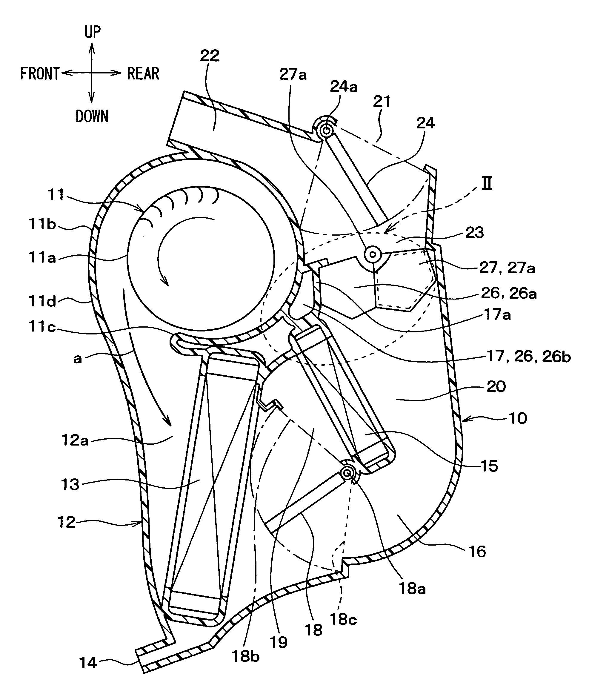
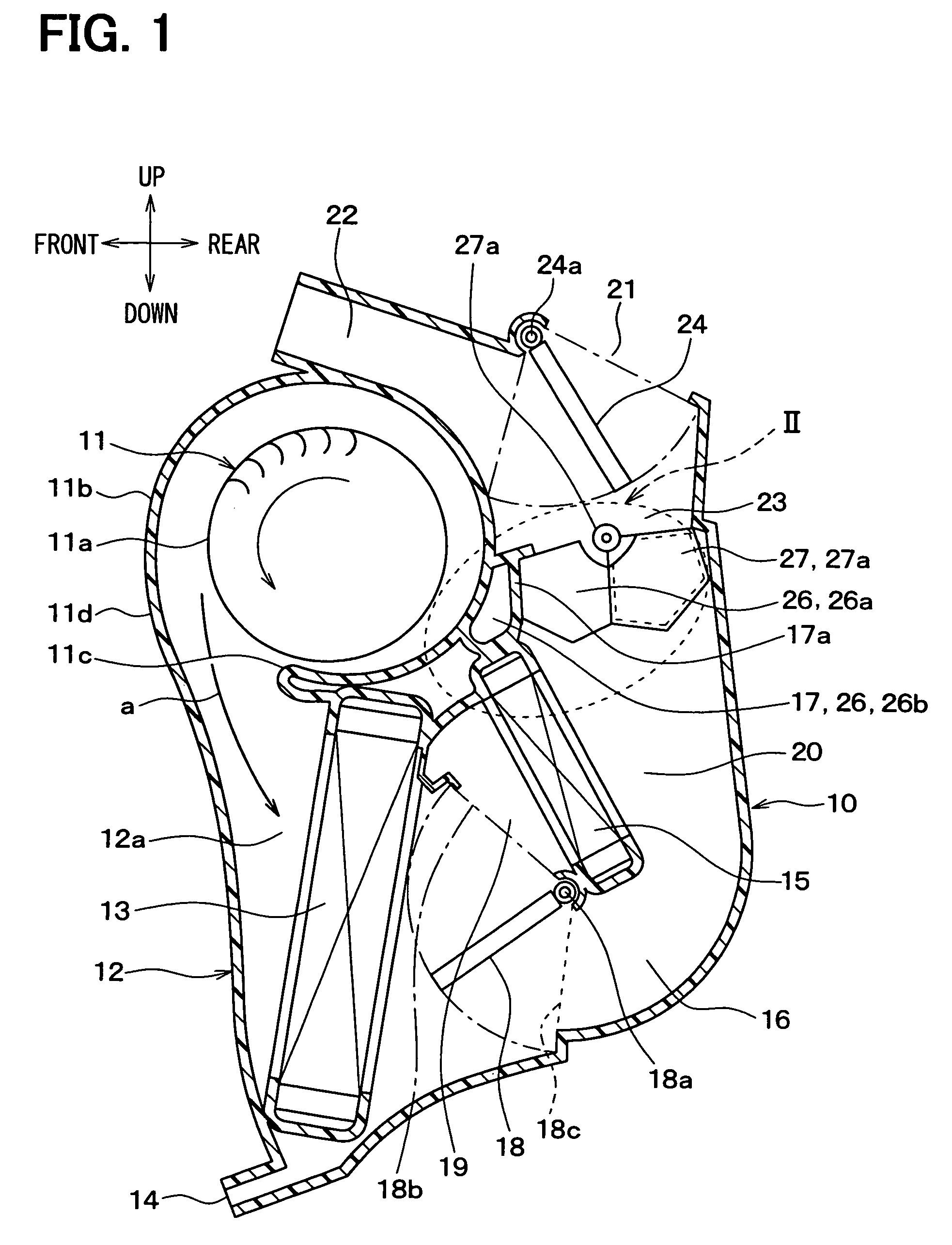
[0023]A first embodiment of the present invention will be described with reference to FIGS. 1 to 3C. Referring to FIG. 1, an interior unit 10 of a vehicular air conditioning apparatus is mounted in a space provided inside of an instrument panel that is located at a front part of a passenger compartment of a vehicle, and at a substantially middle position with respect to a vehicle right and left direction. In FIG. 1, an up and down arrow and a front and rear arrow denote respective directions when the interior unit 10 is mounted in a vehicle. Also, a direction perpendicular to a paper surface of FIG. 1 corresponds to the right and left direction of the vehicle, which is also referred to as a vehicle width direction.

[0024]The interior unit 10 has a blower 11 at a front upper position. The blower 11 includes a fan 11a, a motor (not shown) for driving the fan 11a, and a scroll casing 11b. For example, the fan 11a is a centrifugal multi blade fan, such as a sirocco fan. The scroll casing...

second embodiment

[0079]A second embodiment will now be described with reference to FIGS. 4A and 4B. Hereinafter, like components are denoted by like reference characters and a description thereof is not repeated.

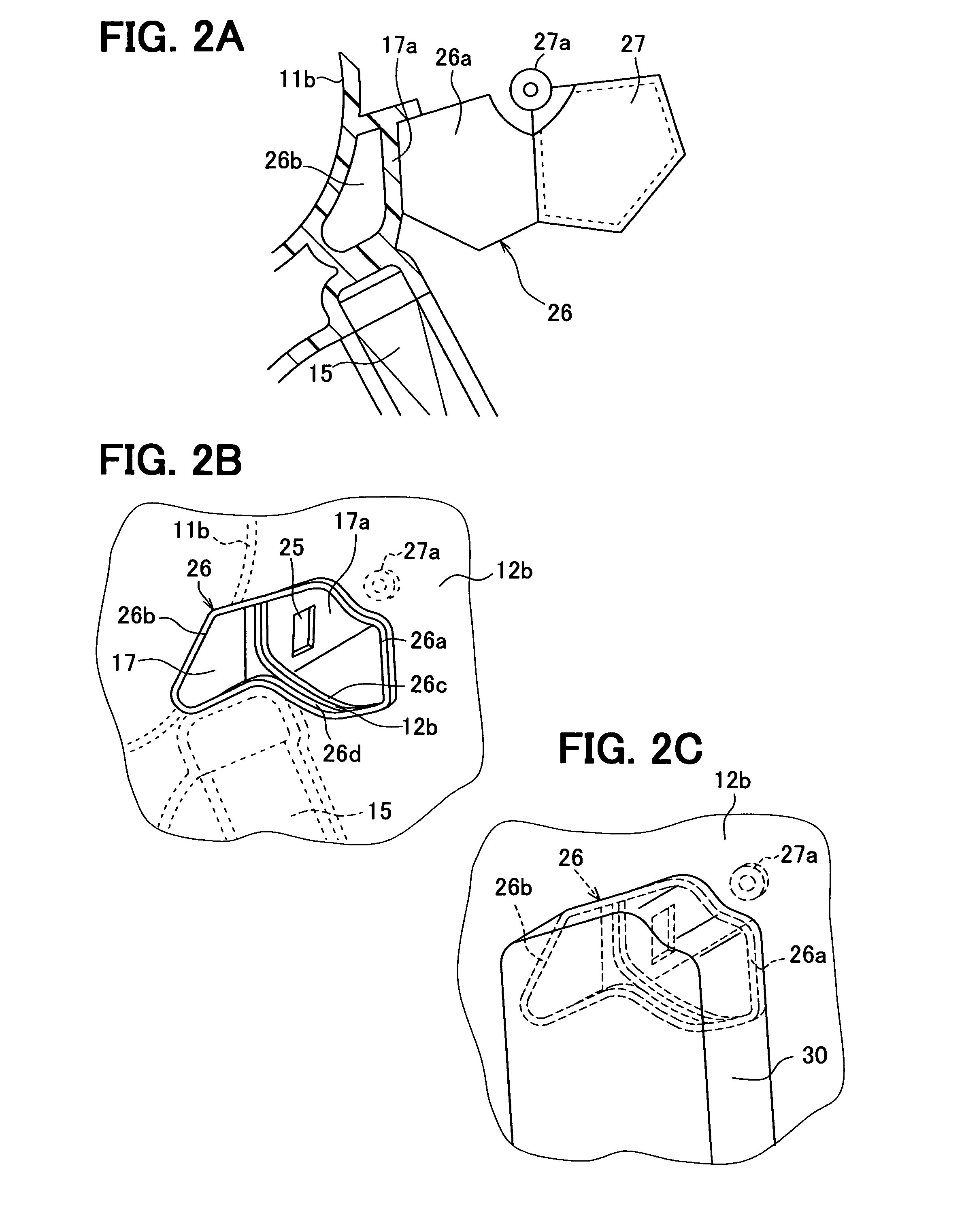
[0080]In the first embodiment, the communication portion 25 is provided by two openings formed adjacent to opposite ends of the passage wall 17a with respect to the vehicle right and left direction. In the second embodiment, the communication portion 25 is provided by a single opening that has a rectangular shape extending in a longitudinal direction of the passage wall 17a, such as in the vehicle right and left direction, as shown in FIG. 4A. In this case, the foot door 27 has a single second door portion 27c for opening and closing the opening of the communication portion 25, as shown in FIG. 4B. The second door portion 27c has a rectangular shape and extends between the first door portions 27b. The second sealing member 29 has a shape corresponding to the opening of the communication port...


PUM


Abstract

An air conditioning apparatus has a blower, a unit case, a cooling heat exchanger and a heating heat exchanger. The heat exchangers are disposed in the unit case such that ends thereof are adjacent to the blower. The unit case has a side opening on its side wall and a tubular part between the end of the heating heat exchanger and a casing of the blower. The tubular part has a communication portion for allowing communication between a hollow space provided therein and a space downstream of the second heat exchanger. The unit case has a passage opening at an end of the tubular part and adjacent to the side opening for allowing the air introduced in the hollow space to flow out from the hollow space. Further, a door is provided in the unit case to open and close the side opening and the communication portion simultaneously.

Description

CROSS REFERENCE TO RELATED APPLICATION[0001]This application is based on Japanese Patent Application No. 2007-143575 filed on May 30, 2007, the disclosure of which is incorporated herein by reference.FIELD OF THE INVENTION[0002]The present invention relates to an air conditioning apparatus for a vehicle.BACKGROUND OF THE INVENTION[0003]With regard to an air conditioning apparatus for a vehicle, in general, a blower, a cooling heat exchanger and a heating heat exchanger are arranged closed to each other in an air conditioning case, so as to reduce an overall size of the apparatus and pressure loss of air flowing in the air conditioning case.[0004]For example, with regard to a vehicular air conditioning unit described in U.S. Pat. No. 5,950,711, a cooling heat exchanger is inclined such that an air introducing surface of a core faces an upper space and a heating heat exchanger is inclined such that an air introduction surface of a core faces a lower space, in an air conditioning case....

Claims


Application Information

Patent Timeline
Patent Type & Authority Patents(United States)
IPC IPC(8): B60H3/00B60H1/00F25B13/00
CPCB60H1/00028B60H1/00671B60H2001/00192
Inventor SHINDOH, TOMOHIDE
Owner DENSO CORP
Why Eureka
Try Eureka