Clothes drying machine with improved vapour injection arrangement

a clothes drying machine and vapour injection technology, applied in the direction of lighting and heating equipment, washing apparatus, applications, etc., can solve the problems of unfailingly occurring that such liquid particles enter the drum, high temperature of approx, and clearly visible halo-like marks

Active Publication Date: 2011-12-27
ELECTROLUX HOME PROD CORP NV
View PDF9 Cites 5 Cited by
  • Summary
  • Abstract
  • Description
  • Claims
  • Application Information

AI Technical Summary

Benefits of technology

[0014]It would therefore be desirable, and is a main object of the present invention, actually, to provide a clothes drying machine of the aforementioned kind, which is provided with means for dispersing the gaseous substances that—as mixed with minute liquid fractions—are sprayed into a container, i.e. the rotating drum, in view of carrying out particular processes aimed at treating the clothes and garments loaded in said drum under admission of appropriate fluid substances in the form of gases or vapours, wherein such drying machine is also provided with means adapted to do away with any possibility for not only small liquid droplets, but also even rather copious sprays of liquid mixed with vapour to be able to enter the drum and reach the clothes loaded thereinto jointly with the stream of gas / vapour.

Problems solved by technology

However, these particular manners of carrying out the above-described treatment processes, while inherently simple and effective, have turned out as being peculiar in showing up some practical drawbacks.
In other words, they share a peculiarity in that, when said fluid is a gas or vapour mixture that also contains some droplets of a liquid substance, or when the gas / vapour is generated for instance in a rather remotely located boiler and, while flowing through the supply conduit leading it to the drum for injection thereinto, cools down and undergoes partial condensation when reaching the above-mentioned nozzle, it unfailingly occurs that such liquid particles enter the drum as such.
1) a first such drawback may for instance arise from the fact that, when the treatment is being carried out on a load of delicate and coloured clothes and garments, which are generally known to have to be handled at temperatures ranging from 40° C. to 60° C. max. when washed and dried, the rather high temperature of approx.
2) a second drawback is due to the fact that, owing to such treatment being generally carried out following a drying cycle, or being otherwise an isolated process that is carried out independently and, therefore, is not followed by any other treatment, it may well occur that the liquid particles reaching the garments being handled tend to settle thereonto and, while eventually drying up, they nevertheless leave a clearly visible halo-like mark that tend to persist there even after the garments are removed from the drum; the ultimate result is that the treated clothes may eventually take up an appearance that looks even worse than the one they had before being treated for freshening up, wherein quite markedly perceivable are in particular the small spots caused by the aforementioned liquid droplets;
3) a third drawback is in connection with the actual safety of the user of the drying machine: the liquid droplets issuing from the ejection nozzle according to the prior art may in fact keep dripping from said nozzle for a short period of time even after the end of the treatment process, i.e. when the loading door of the machine can be opened so as to enable the user to introduce his / her hands into the drum in view of removing the treated clothes therefrom; in such circumstance, it quite frequently occurs that said droplets fall to hit the hand of the user as it reaches out under the nozzle, and—owing to such droplets being at a temperature of approx.
90° C.—they certainly expose the user to dangerous scalding problems.

Method used


Image

  • Clothes drying machine with improved vapour injection arrangement
  • Clothes drying machine with improved vapour injection arrangement
  • Clothes drying machine with improved vapour injection arrangement

Examples


Embodiment Construction

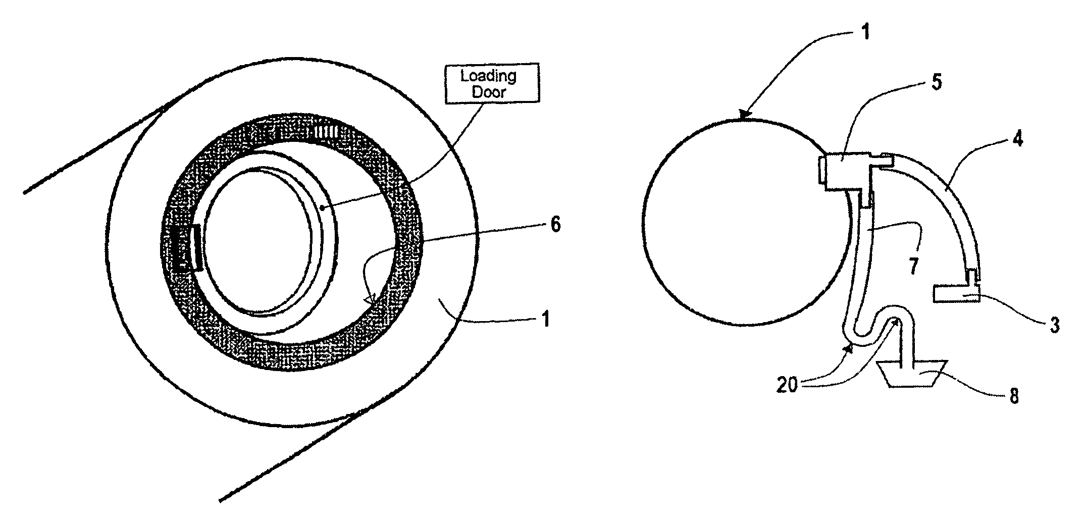
[0023]With reference to FIGS. 1, 2 and 6, a clothes drying machine according to the present invention comprises a rotating drum 1 provided to hold the clothes to be dried, across which a stream of hot air is able to flow through a proper conduit generally known as such in the art. The moisture removed from the clothes being dried by said stream of hot air is eventually let out of the drum and off into the outside atmosphere through a second conduit (not shown).

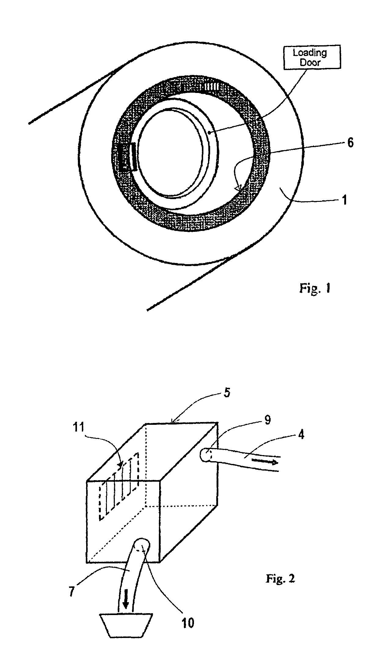
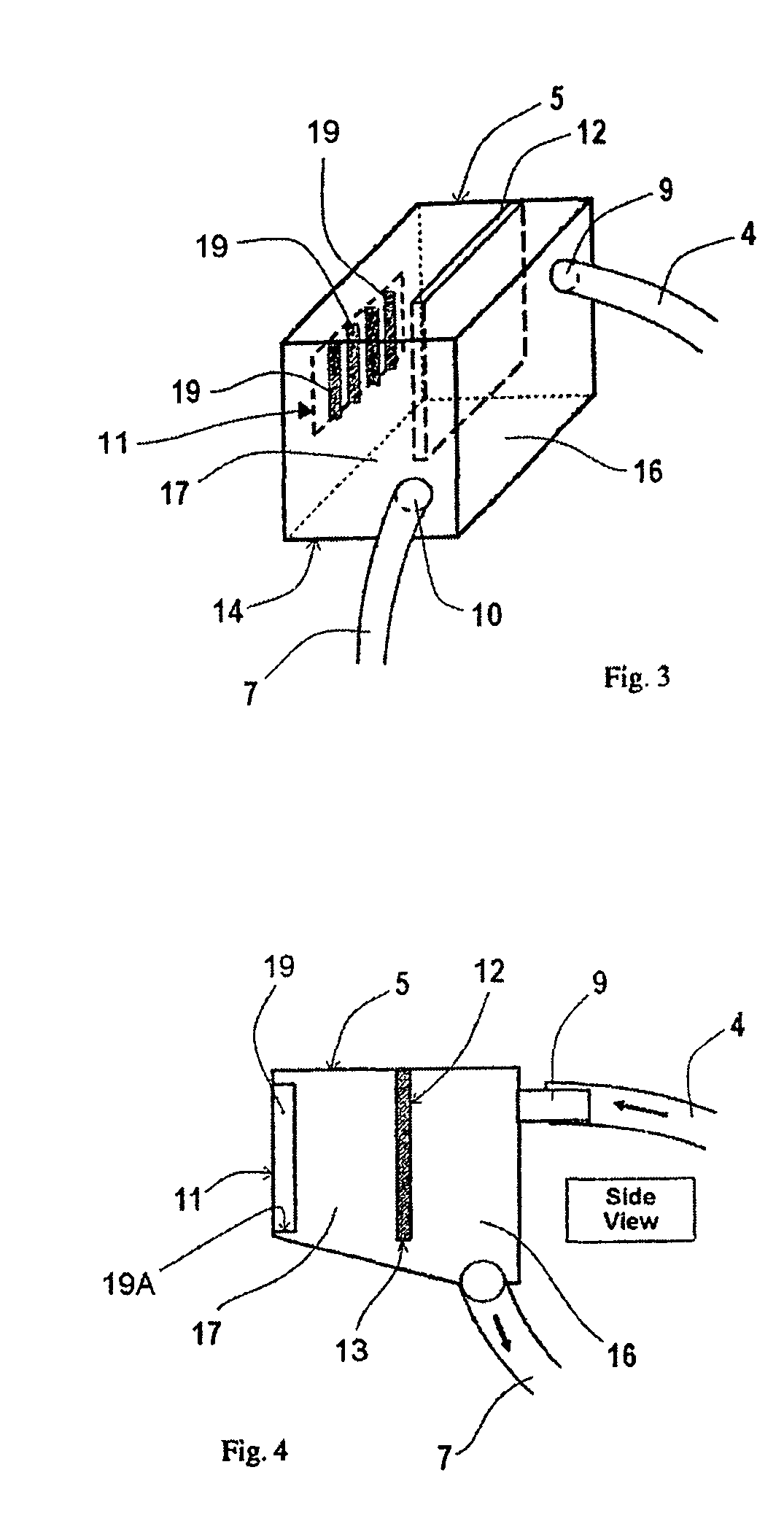
[0024]Within the drying machine there is located also a boiler 3 that heats up the water contained therein and—via a first pipe conduit 4—delivers the steam generated by it to a suitably configured ejection cell 5 located inside the same machine in a position close to the inward edge of the loading aperture 6 of the drum, so as to directly communicate with the interior of the same drum.

[0025]Branching off from said ejection cell 5 there is a second drain pipe conduit 7, the inflow port of which is configured in a manner so as ...


PUM


Abstract

Household-type clothes drying machine provided with a rotating drum (1), first means adapted to circulate a stream of drying air through said drum and comprising an appropriate inflow conduit and an outflow conduit for said air stream, second means (3) adapted to generate a gas or vapour stream, a first delivery pipe conduit (4) connecting said second means with an ejection arrangement located on the inner surface of the loading door of the drum, a second drain pipe conduit (7) adapted to collect the condensed moisture from said ejection arrangement and convey it into a collecting container; said ejection arrangement comprises a substantially sealed cell that is however provided with a first port (9) to enable the gas/vapour stream to flow in from said first delivery pipe conduit, a second port (10) to enable liquid and condensate to flow into said drain pipe conduit, and an ejection window (11) that opens into the interior of said drum and is adapted to eject said gas/vapour stream flowing in from said first delivery pipe conduit. Inside said cell there is provided a vertically extending wall and said first port is oriented towards said wall, which terminates with a free lower, edge projecting onto the bottom of said cell.

Description

BACKGROUND OF THE INVENTION[0001]The present invention relates to an improved kind of clothes drying machine, preferably of the type intended for use in households, adapted to perform operating cycles for handling laundry items loaded in the rotating drum thereof by letting a fluid medium, such as in particular a gas or, still more particularly, steam, i.e. water vapour, or again steam carrying minute particles of condensed water mixed therewith, into said drum holding the laundry items.[0002]While reference will be generally made to a jet of steam in the following description when talking of such fluid or medium due to be injected in the laundry holding drum, this shall in all cases be understood as meaning that such medium may be any fluid mixture—prevailingly in the state of a gas—containing any of a number of other substances, such as detergents, scents, disinfectants, and the like.[0003]Largely known is the possibility for garments and clothes in general, but the most delicate ...

Claims


Application Information

Patent Timeline
Patent Type & Authority Patents(United States)
IPC IPC(8): F26B3/34
CPCD06F58/26
Inventor PARUZZOLO, GIOVANNICIMETTA, SILVANO
Owner ELECTROLUX HOME PROD CORP NV
Why Eureka
Try Eureka