Conveyer apparatus

a conveyer and footstep roller technology, applied in the direction of conveyers, escalators, transportation and packaging, etc., can solve the problems of reducing the size and reducing the efficiency of the conveyer. , to achieve the effect of suppressing the velocity unevenness of the footstep roller, reducing the thickness of the conveyer apparatus, and reducing the thickness of the conveyer

Active Publication Date: 2011-12-27
TOSHIBA ELEVATOR KK
View PDF34 Cites 5 Cited by
  • Summary
  • Abstract
  • Description
  • Claims
  • Application Information

AI Technical Summary

Benefits of technology

[0012]The present invention is invented in consideration of the conventional situation mentioned above and therefore, it is an object of the present invention to provide a conveyer apparatus which effectively suppresses the velocity unevenness of footstep rollers in order to assure the comfortable ride quality and which allows a thickness of the apparatus to be reduced as a whole.
[0014]In this conveyer apparatus, when the rotating device is driven, the drive sprocket rotates on receipt of a driving force of the rotating device, so that the driving force of the rotating device is transmitted to the footstep chain due to the rotation of the drive sprocket. The drive of the footstep chain allows respective footsteps rollers of the plural footsteps connected with each other through the footstep chain to move along the footstep guide rail in circulation. Then, the footstep rollers move on the horizontal surface of the footstep guide rail, which is set at a level on a position obtained by addition the designated offset to the tangential line of the drive sprocket and subsequently move from the reference position closest to the drive sprocket along the curved part, into the meshing condition with the drive sprocket. As a result, velocity unevenness of a preceding footstep roller is absorbed and the velocity unevenness is not transmitted to a following footstep roller, thereby keeping the moving velocity of the footstep rollers at a substantial average velocity. Thus, with restriction of vibration caused by the velocity unevenness of the footstep rollers, it is possible to make sure of comfortable ride quality about the conveyer apparatus. Additionally, with no need of establishing such a great value for the offset, it is advantageous in realizing the thin formation of the apparatus. Moreover, if establishing an optimal value for the offset, then it is possible to provide the curved part of the footstep guide rail with the profile of a falling contour that gently falls from the horizontal surface to the meshing position of the drive sprocket. Such a profile does not cause the footstep rollers to float and therefore, there is no need to provide a pusher member for preventing the floating of the footstep rollers.
[0015]Without applying only to the introductory side of the drive sprocket, the curved part is also applicable to a footstep guide rail having a straight part and an arc part, in detail, a changing portion from the straight part to the arc part. That is, provided that the straight part of the footstep guide rail is established at a level position obtained by adding a designated offset and that the footstep guide rail is provided, at a changing portion from the straight part to the arc part, with a curved part as mentioned above so that the footstep rollers moving along the straight part of the footstep guide rail can reach the arc part through the curved part and subsequently move along the arc part, it is possible to absorb the velocity unevenness of the footstep guide rail effectively, restraining vibration of the footsteps and also possible to ensure comfortable of ride quality about the apparatus.
[0017]Instead of establishing the straight part of the footstep guide rail at a level as a result of adding a designated offset, alternatively, if subtracting a designated offset from a radius curvature of the arc part of the footstep guide rail and additionally providing a similar curved part in a changing portion from the straight part to the arc part of the footstep guide rail, it is possible to absorb the velocity unevenness of the footstep guide rail effectively, restraining vibration of the footsteps and also possible to ensure comfortable of ride quality about the apparatus.

Problems solved by technology

However, if such a small-diameter sprocket is employed as the drive sprocket of the chain drive mechanism, then a problem arises in that great unevenness is produced in the velocity of the footstep rollers linked by the footstep chain, being actualized in the form of vibrations of the footsteps and further deteriorating the ride quality of the conveyer apparatus.
However, since a level of the horizontal surface of the footstep guide rail is relatively higher than the drive sprocket, the same art has a disadvantage in obtaining a minimized size of the whole conveyer apparatus.
Such an increase in the interval ho causes the truss to be large-sized, producing an obstacle in obtaining a minimized size of the whole conveyer apparatus.
Therefore, it results in spoiling the space-saving effect that is brought by reducing the pitch-circle diameter of the drive sprocket down as far as 348.4 mm.

Method used


Image

  • Conveyer apparatus
  • Conveyer apparatus
  • Conveyer apparatus

Examples


Embodiment Construction

[0029]Embodiments of the present invention will be described below, with reference to accompanying drawings.

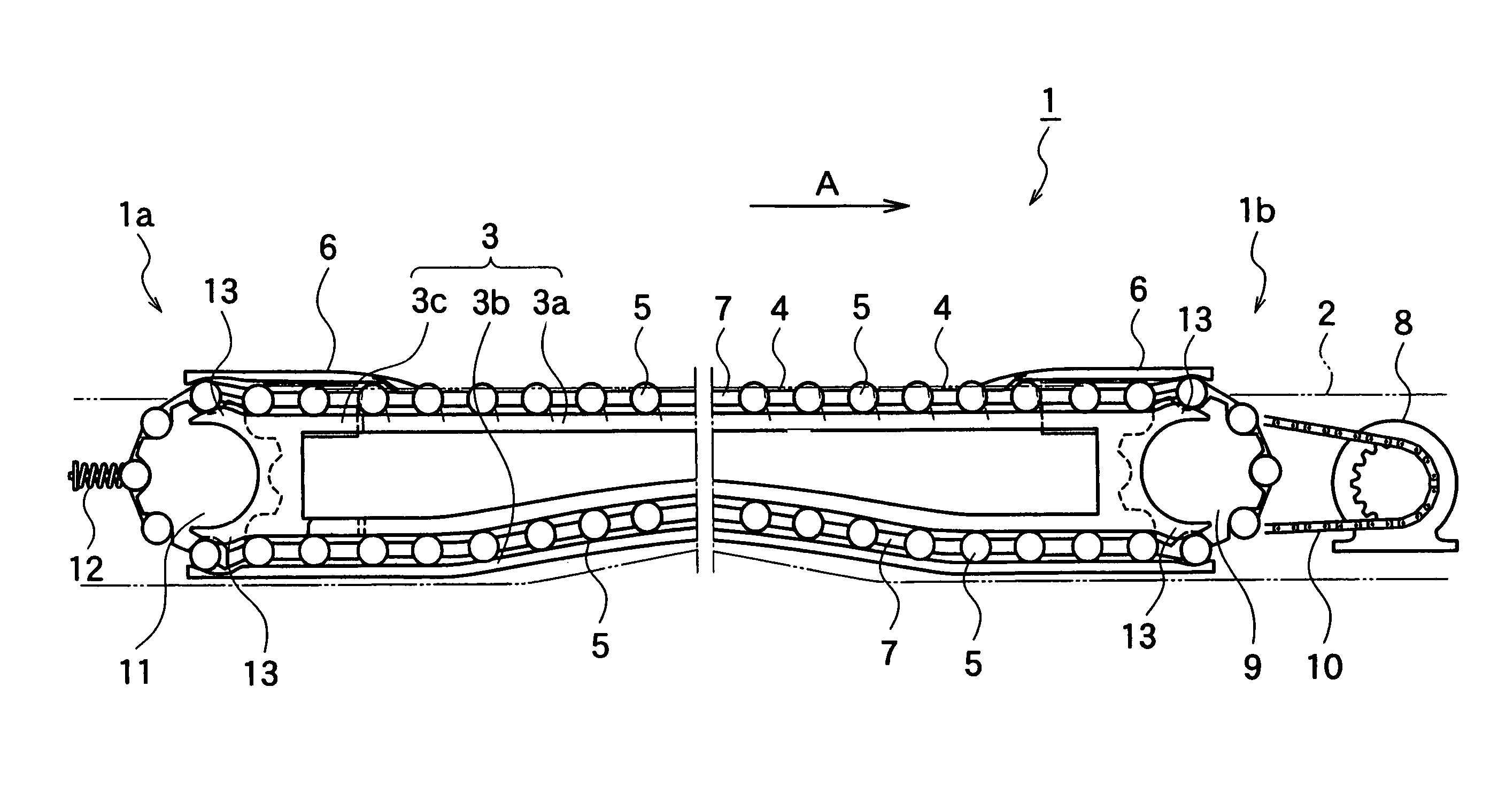
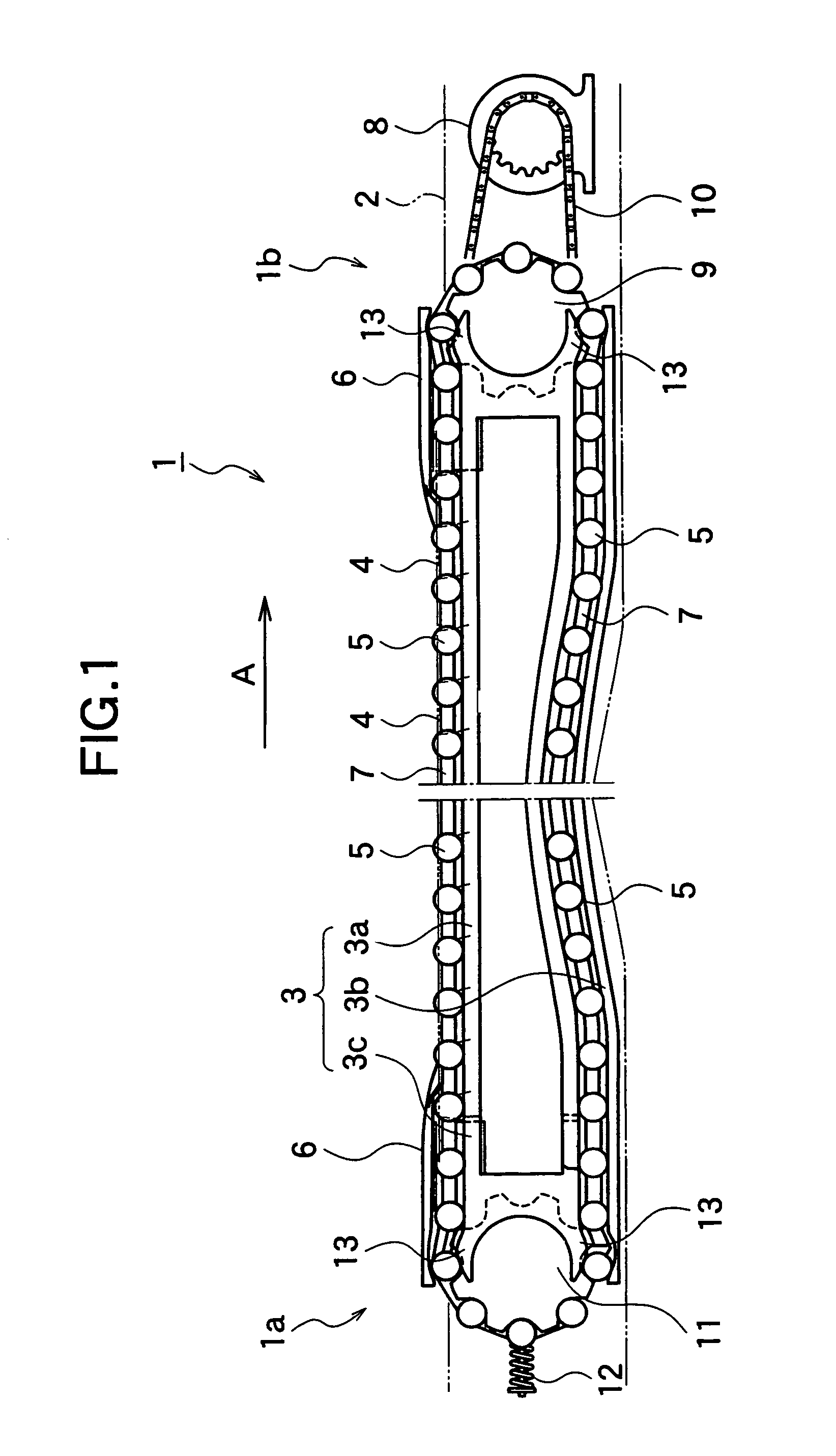
[0030]FIG. 1 shows the whole constitution of a conveyer apparatus of the present invention schematically. The shown conveyer apparatus 1 of FIG. 1 is constructed as a moving walkway that is arranged substantially horizontally to a road surface to convey passengers. The conveyer apparatus 1 includes a structure 2 called “truss” for supporting its own weight and loads of the passengers. This structure 2 is accommodated in a pit that is disposed below the road surface.

[0031]In the structure 2, a footstep guide rail 3 is arranged so as to go around from an entrance 1a to an exit 1b of the conveyer apparatus 1. This footstep guide rail 3 is provided to guide the movement of a plurality of footsteps 4 conveying passengers thereon. That is, the footsteps 4 are provided with footstep rollers 5, respectively. With the movement of the footstep rollers 5 along the footstep guide rail 3, ...


PUM


Abstract

A footstep guide rail (3) (rail body 3a) is arranged so that a level H of a horizontal surface is set at the position obtained by adding a designated offset δ to a tangential line L of a drive sprocket (9) and the footstep guide rail (3) is provided, at its one end on an introductory side of the drive sprocket (9), with a curved part (13). At a reference position closest to the drive sprocket (9), the horizontal surface of the footstep guide rail (3) is changed to the curved part (13). Consequently, it is possible to absorb velocity unevenness of one footstep roller approaching the drive sprocket (9).

Description

[0001]The present application is a continuation of U.S. application Ser. No. 11 / 402,256, filed Apr. 12, 2006, which is a continuation of U.S. application Ser. No. 10 / 536,252, filed May 25, 2005, the entire contents of which are incorporated herein by reference.TECHNICAL FIELD[0002]The present invention relates to a conveyer apparatus, such as an escalator and a moving walkway.BACKGROUND ART[0003]A conveyer apparatus, such as an escalator and a moving walkway, includes a plurality of footsteps provided with footstep rollers. Since these plural footsteps are linked to each other at predetermined pitches through an endless footstep chain, the footsteps are integrated with the footstep chain. Since the footstep chain is driven by a chain drive mechanism, all the foot steps can move synchronously without leaving any space between the footsteps. Additionally, with the engagement of the plural footstep rollers with a footstep guide rail disposed in a structure, these footsteps move between...

Claims


Application Information

Patent Timeline
Patent Type & Authority Patents(United States)
IPC IPC(8): B66B21/00B66B21/02B66B23/14B65G21/22B66B23/02
CPCB66B23/022B65G21/22B66B23/08B66B23/14B66B23/26
Inventor ISHIKAWA, YOSHINOBUMUNAKATA, TADASHIOGIMURA, YOSHIOTESHIMA, NOBUHIKONAKAGAKI, SHIGEOKAWAMOTO, HITOSHIFUJII, KENICHIIKEDA, YOSHIFUMIHARA, KAZUHISAKIKUCHI, TAKAYUKI
Owner TOSHIBA ELEVATOR KK
Why Eureka
Try Eureka