Multi-fingered robotic hand

a multi-fingered, robotic hand technology, applied in the field of robotic hands, can solve the problem of complex structure of the robotic hand

Inactive Publication Date: 2011-12-27
HONG FU JIN PRECISION IND (SHENZHEN) CO LTD +1
View PDF5 Cites 17 Cited by
  • Summary
  • Abstract
  • Description
  • Claims
  • Application Information

AI Technical Summary

Problems solved by technology

However, the structure of the robotic hand tends to be complicated and fraught with associated design problems with manufacturing process simplicity and cost implications.

Method used


Image

  • Multi-fingered robotic hand
  • Multi-fingered robotic hand
  • Multi-fingered robotic hand

Examples


Embodiment Construction

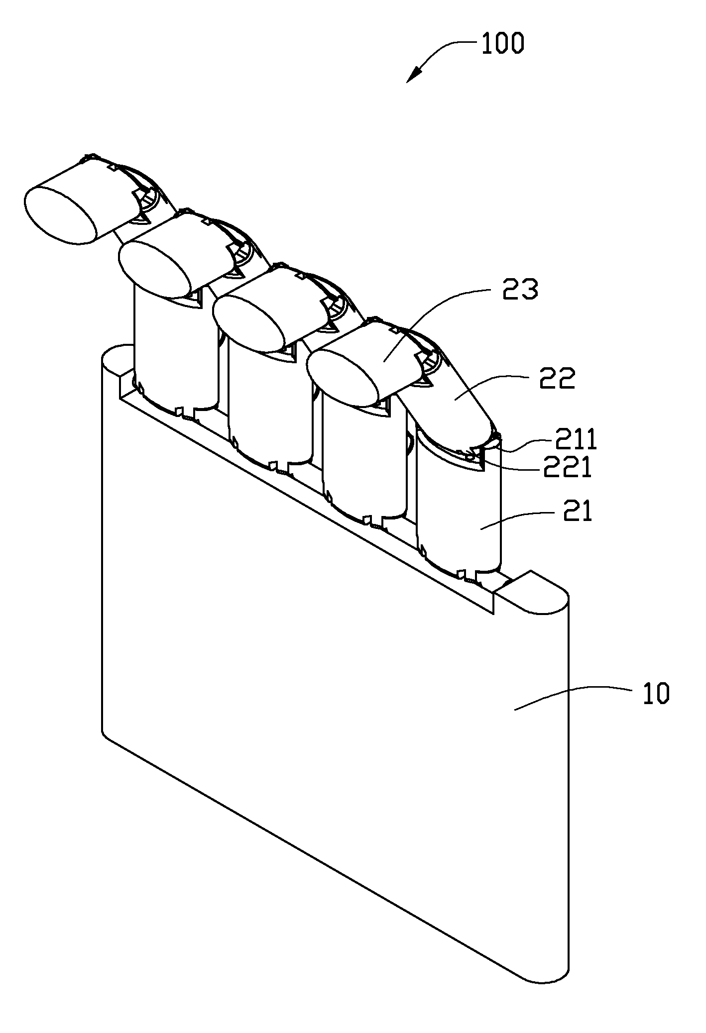
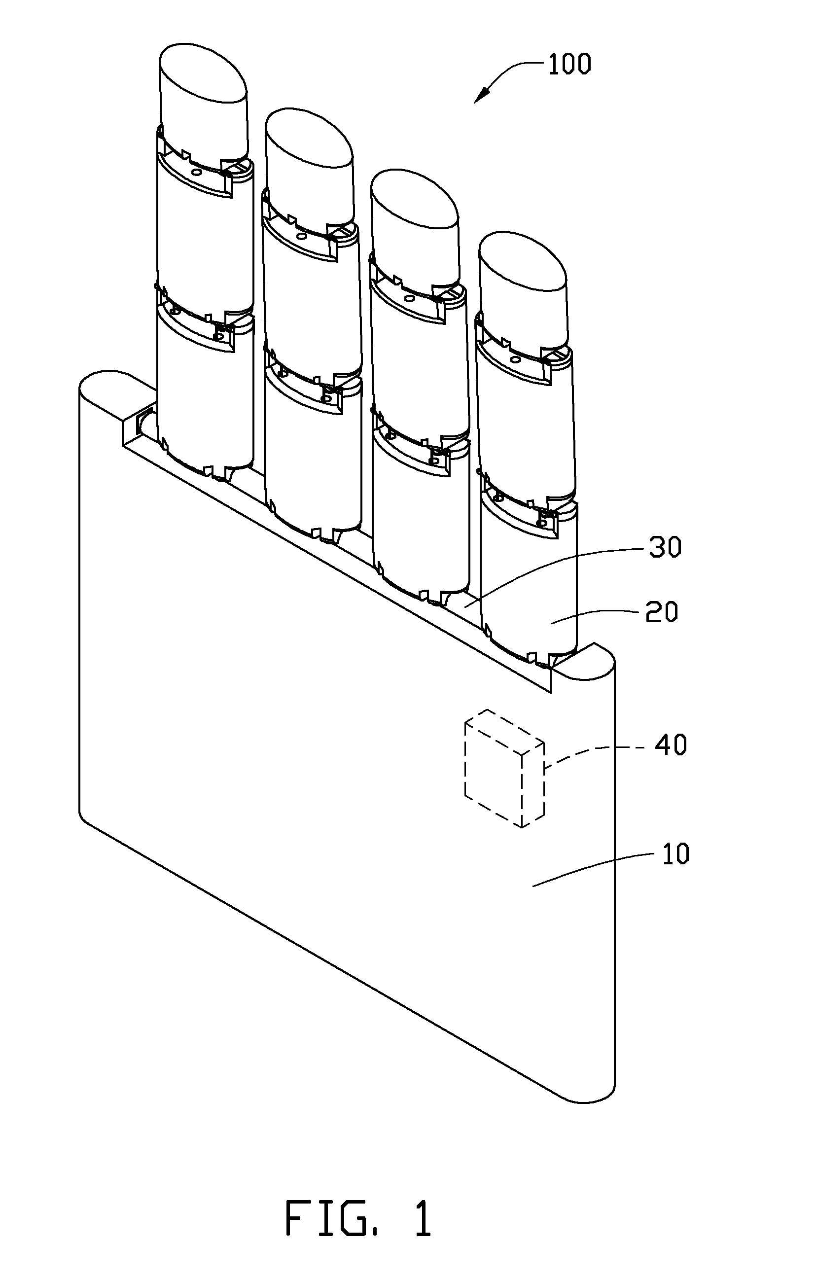
[0012]Referring to FIG. 1, a robotic hand 100 includes a base 10, a plurality of digits 20, and a rotation member 30. The rotation member 30 is rotatably connected to the base 10. The digits 20 are fixedly connected to the rotation member 30, which enables the digits 20 to rotate relative to the base 10. The rotation member 30 is driven by a driving means 40, such as an electrical motor. Although not shown, the robotic hand 100 may also include a transmission device that is coupled to the driving means 40 and the rotation member 30. The transmission device may be used to transmit the rotational motion from the driving means 40 to the rotation member 30.

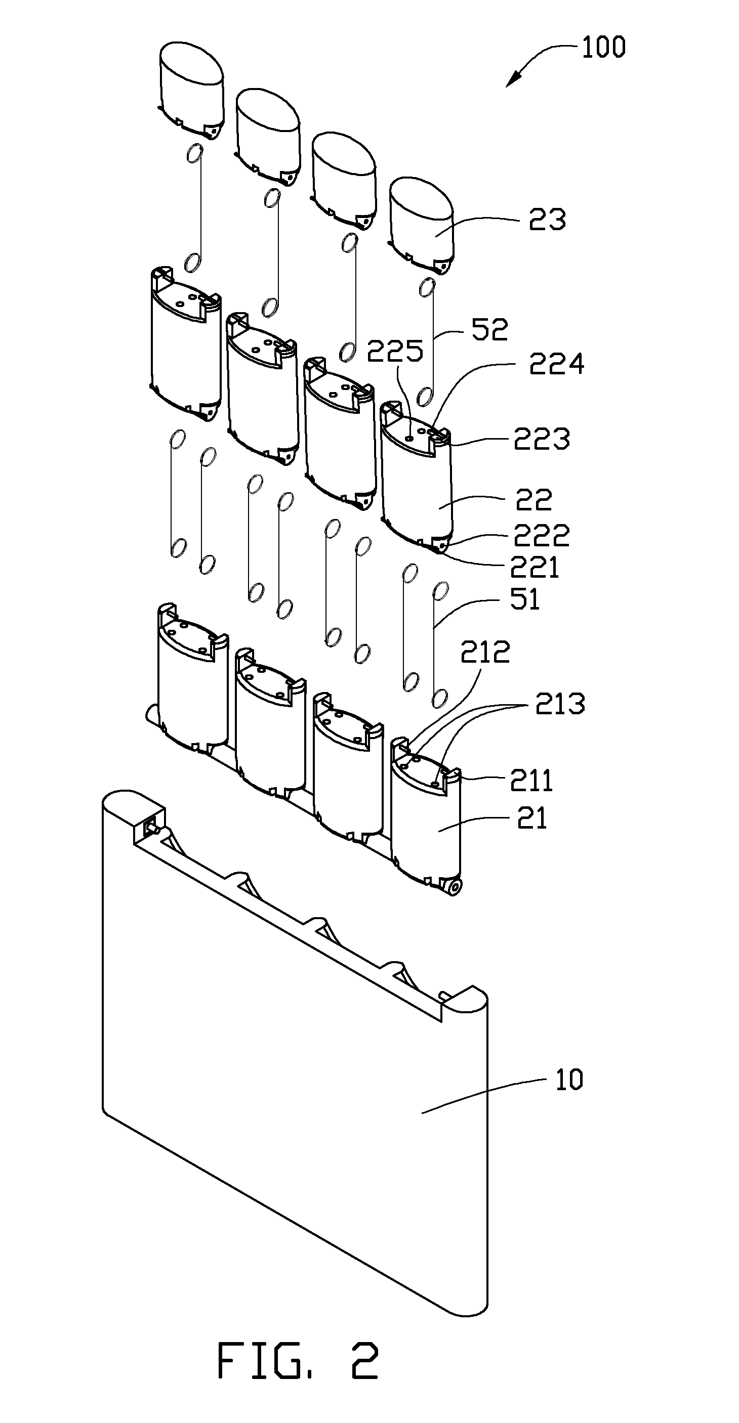
[0013]Referring to FIGS. 2 and 3, each of the digits 20 is constructed in the same manner and resembles fingers of a human hand, which includes a proximal phalanx 21, a middle phalanx 22, and a distal phalanx 23. One end of the proximal phalanx 21 is fixedly connected to the rotation member 30. The other end of the proximal phalanx 21...


PUM


Abstract

A multi-fingered robotic hand comprises a base, a rotation member rotatably connected to an end of the base, a driving means, and a plurality of digits. The driving means is configured for driving the rotation member to rotate. Each digit comprises a proximal phalanx, a middle phalanx and a first transmission member. The proximal phalanx is connected to the rotation member. The middle phalanx is rotatably connected to the proximal phalanx. The first transmission member includes two ends respectively attached to the proximal phalanx and the middle phalanx, wherein the first transmission member is configured for transmitting rotation of the proximal phalanx to the middle phalanx.

Description

BACKGROUND[0001]1. Technical Field[0002]The present disclosure relates to robotic hands and, more particularly, to a multi-fingered robotic hand.[0003]2. Description of Related Art[0004]Manipulable hand-like apparatuses are utilized in several industries. One such apparatus is a multi-fingered robotic hand. The multi-fingered robotic hand includes a plurality of digits capable of performing certain grasping operations. The multi-fingered robotic hand generally includes a plurality of motors to drive the digits. However, the structure of the robotic hand tends to be complicated and fraught with associated design problems with manufacturing process simplicity and cost implications.[0005]Therefore, a new type of robotic hand is required to overcome the above-mentioned problems.BRIEF DESCRIPTION OF THE DRAWINGS[0006]The components in the drawings are not necessarily drawn to scale, the emphasis instead being placed upon clearly illustrating the principles of the multi-fingered robotic h...

Claims


Application Information

Patent Timeline
Patent Type & Authority Patents(United States)
IPC IPC(8): B66C1/00
CPCB25J15/0009
Inventor YUAN, HUI
Owner HONG FU JIN PRECISION IND (SHENZHEN) CO LTD
Why Eureka
Try Eureka