Bracket for a lighting fixture in a suspended ceiling

a technology for suspended ceilings and brackets, which is applied in fixed installation, lighting and heating apparatus, and support devices for lighting and heating, etc. it can solve the problems of not being able to change the louver to a new optic without changing the fixture itself, and the model fixture does no

Inactive Publication Date: 2011-12-27
ALP LIGHTING & CEILING PROD INC
View PDF11 Cites 33 Cited by
  • Summary
  • Abstract
  • Description
  • Claims
  • Application Information

AI Technical Summary

Benefits of technology

[0005]To overcome this problem, one or more embodiments of the present invention provides for an adapter bracket which enables the installation of a door frame or louver into a recessed fixture that sits on a T-bar supported by a ceiling without having to custom design a hinge and latch system to match the original fixture or require the installation of a false frame that lifts the fixture. The brackets slide between the T-bar and the existing fixture. The bracket is also slightly wider than the T-bar opening. The door frame will keep the brackets spaced wide enough to ensure that the assembly would not fall out of the opening. The hinge and latch mechanism for the door frame is built into its end rails and latches onto the bracket to ensure the door frame is supported and held in position.

Problems solved by technology

One problem is that some of the older model fixtures do not include a hinged louver or other type of door frame because the hinge and latch are built into the louver itself.
Therefore, changing the louver to a new optic without changing the fixture itself becomes a difficult task as one cannot simply open a door frame and slide a new fixture in its place.

Method used


Image

  • Bracket for a lighting fixture in a suspended ceiling
  • Bracket for a lighting fixture in a suspended ceiling
  • Bracket for a lighting fixture in a suspended ceiling

Examples


Embodiment Construction

[0030]While the invention is susceptible to embodiments in many different forms, there are shown in the drawings and will be described herein, in detail, the preferred embodiments of the present invention. It should be understood, however, that the present disclosure is to be considered an exemplification of the principles of the invention and is not intended to limit the spirit or scope of the invention and / or claims of the embodiments illustrated.

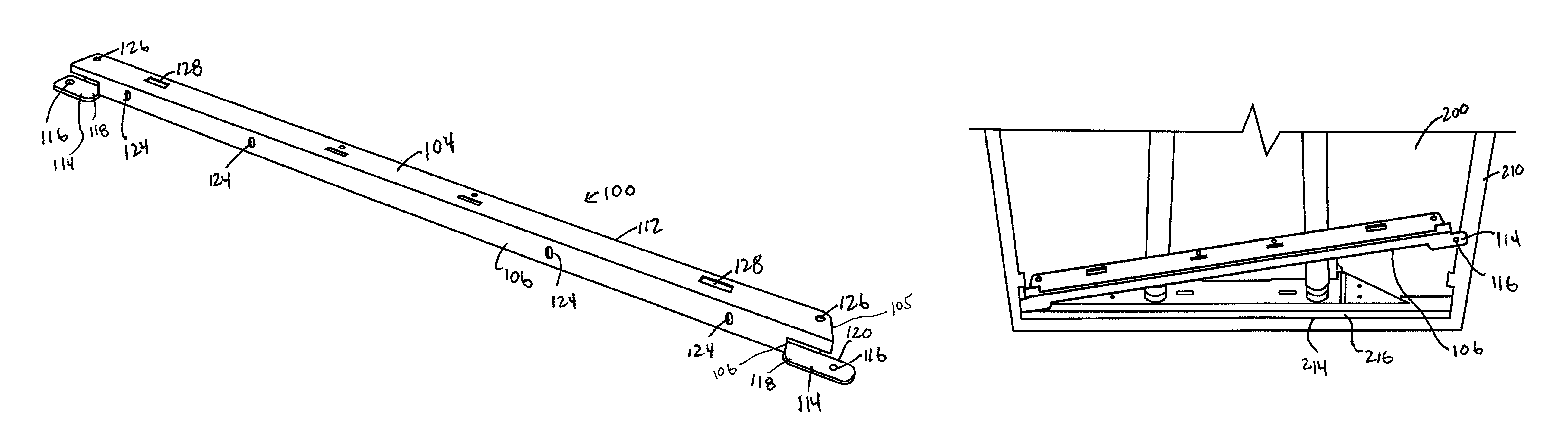
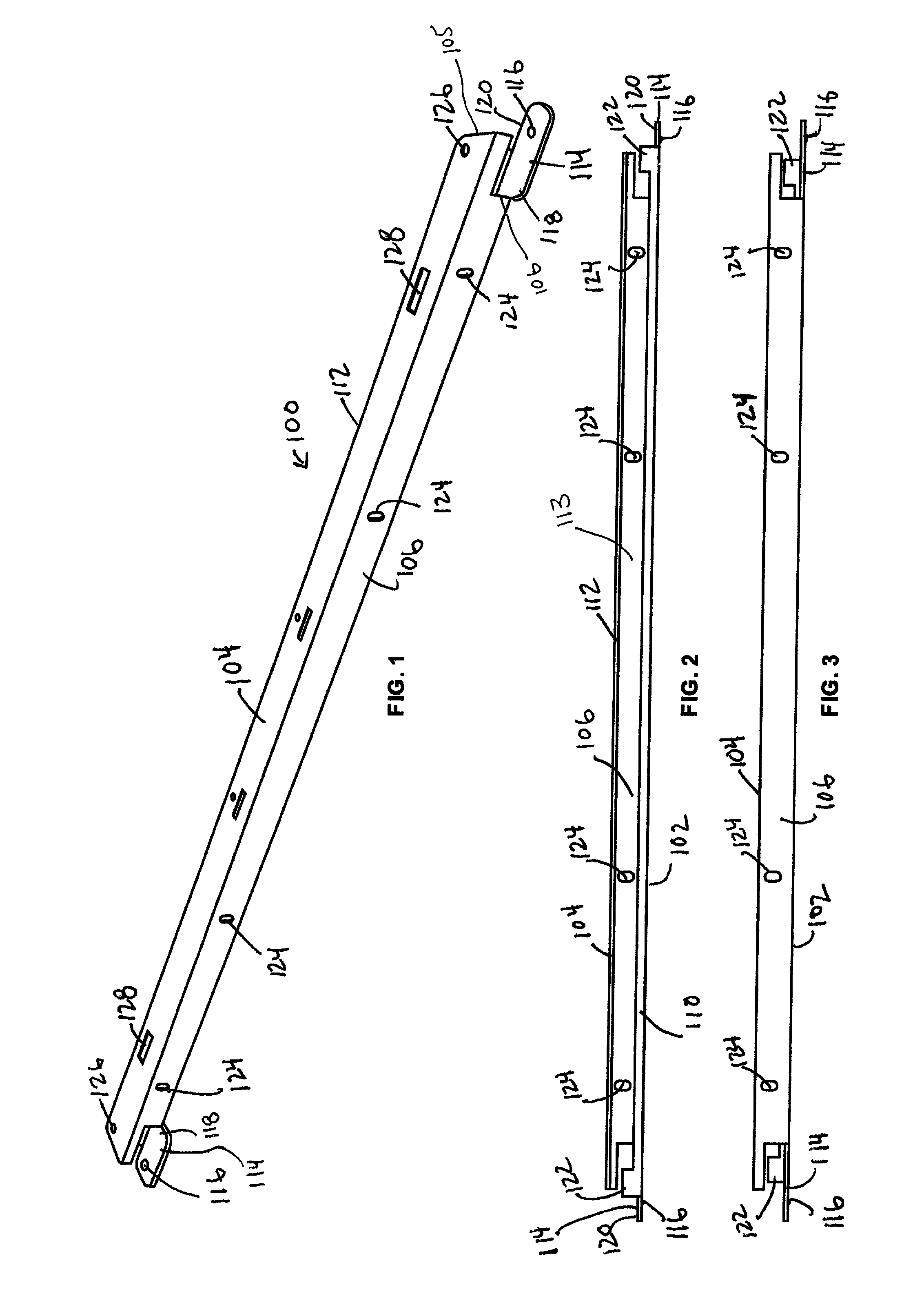
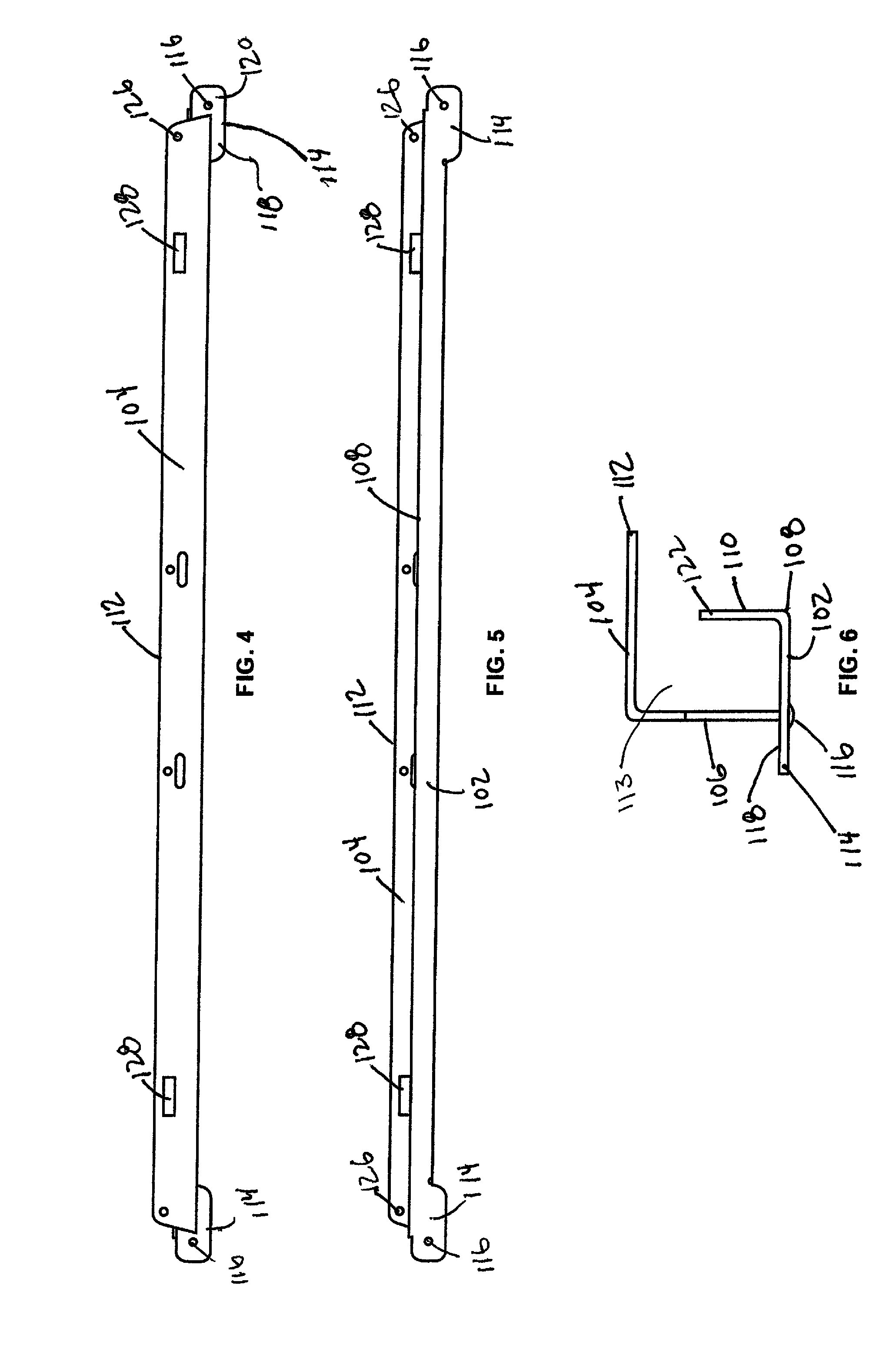
[0031]Referring now to FIGS. 1-7 there is shown an adapter bracket 100 used in connection with one or more embodiments of the present invention. The adapter bracket 100, as described and shown herein, enables the installation of a door frame or louver into a recessed fixture that sits on a T-bar supported by a ceiling. The adapter bracket 100 eliminates the need to custom design a hinge and latch system to match the original fixture and eliminates the need to install a false frame that lifts the fixture. The installation and proper use of...


PUM


Abstract

An adapter bracket which enables the installation of a door frame or louver into a recessed fixture that sits on a T-bar supported by a ceiling without having to custom design a hinge and latch system to match the original fixture or require the installation of a false frame that lifts the fixture. The brackets slide between the T-bar and the existing fixture. The bracket is also slightly wider than the T-bar opening. The door frame will keep the brackets spaced wide enough to ensure that the assembly would not fall out of the opening. The hinge and latch mechanism for the door frame is built into its end rails and latches onto the bracket to ensure the door frame is supported and held in position.

Description

CROSS REFERENCE TO RELATED APPLICATION[0001]This application claim priority and benefit to U.S. Provisional 61 / 056,191 filed May 27, 2008.FIELD OF THE INVENTION[0002]The present invention relates to light fixtures and more particularly to a new bracket used with a light fixture in a suspended ceiling.BACKGROUND OF THE INVENTION[0003]Conventional overhead recessed lighting fixtures or luminaries are designed to conform to suspended ceiling such that the lower edge of the fixture is nearly flush with the underside of the ceiling tiles. The suspended ceilings typically all have a common construction, using inverted T bars suspended from the permanent ceiling above via wires or other structures. The T-bars, which form the suspended ceiling, are laid out to define a grid structure with defined openings between the T-bars. The openings are sized to accommodate ceiling tiles. In addition to the ceiling tiles, lighting fixtures may also be supported by the T-bars.[0004]As the industry advan...

Claims


Application Information

Patent Timeline
Patent Type & Authority Patents(United States)
IPC IPC(8): F21V21/00F21V15/00
CPCF21S8/026F21V17/107F21V3/00F21V11/06
Inventor RICHARDSON, RONALD L.BUCHANAN, III, DALLAS I.SUAREZ, JUAN C.VO, THANH M.
Owner ALP LIGHTING & CEILING PROD INC
Why Eureka
Try Eureka