
Multi-centric orthopedic hinge joint

a multi-centric, hinge joint technology, applied in the field of orthopaedics, can solve the problems of bulky, difficult to adjust, heavy, etc., and achieve the effects of simple, light weight, and unobtrusiveness

Active Publication Date: 2011-12-27
FILLAUER CO INC
View PDF7 Cites 0 Cited by
  • Summary
  • Abstract
  • Description
  • Claims
  • Application Information

AI Technical Summary

Benefits of technology

[0016]Another object is to afford an orthopedic joint that does not utilize a wheel with gear teeth, or a pawl and ratchet mechanism, to achieve a desired angle of rotation. Herein, the motion of each group of outer and inner guide pins, relative to the guide plates, enables rotation between the upper and lower arms of the joint, thereby achieving a range of motion and planetary gear action of a smooth sliding nature resembling normal motion of the body.
[0017]A further object of the invention is to provide an orthopedic joint having versatility and range of motion that is adjustable at many positions.
[0018]Another object is to provide an orthopedic joint that is simple, light weight and unobtrusive.
[0019]A further object of the invention is to provide an orthopedic joint that is adaptable to a highly compact size for infant and pediatric, as well as adult use.

Problems solved by technology

Hinge joints for knee braces in the prior art are bulky, heavy and difficult to adjust.

Method used


Image

  • Multi-centric orthopedic hinge joint
  • Multi-centric orthopedic hinge joint
  • Multi-centric orthopedic hinge joint

Examples


Embodiment Construction

, the Drawings, and the Claims appended herewith.

BRIEF DESCRIPTION OF THE DRAWINGS

[0021]The present invention may be better understood by reference to the following detailed description taken in conjunction with the accompanying drawings, wherein:

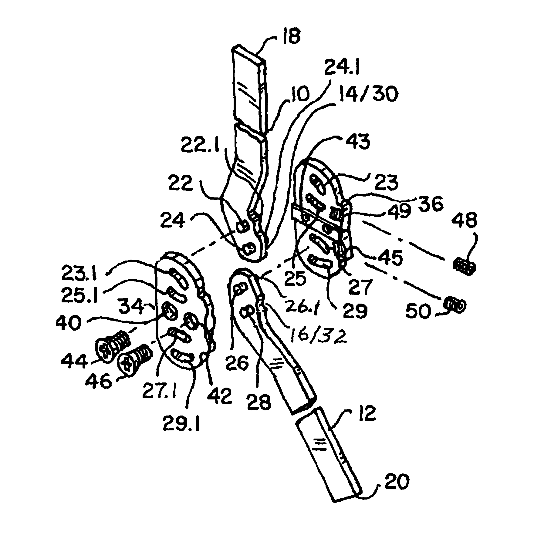
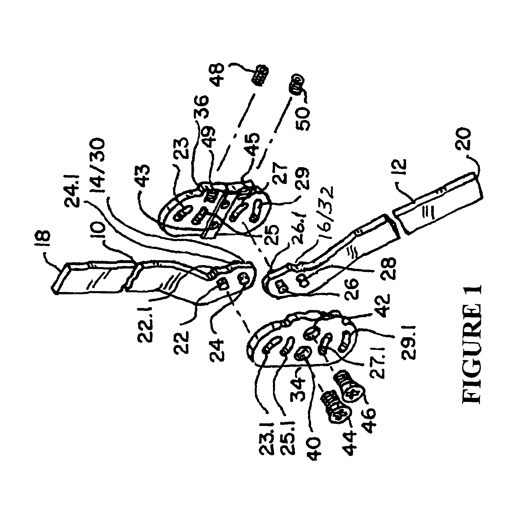
[0022]FIG. 1 is an exploded plan view of the various elements of the multi-centric hinge orthopedic joint of the present invention.

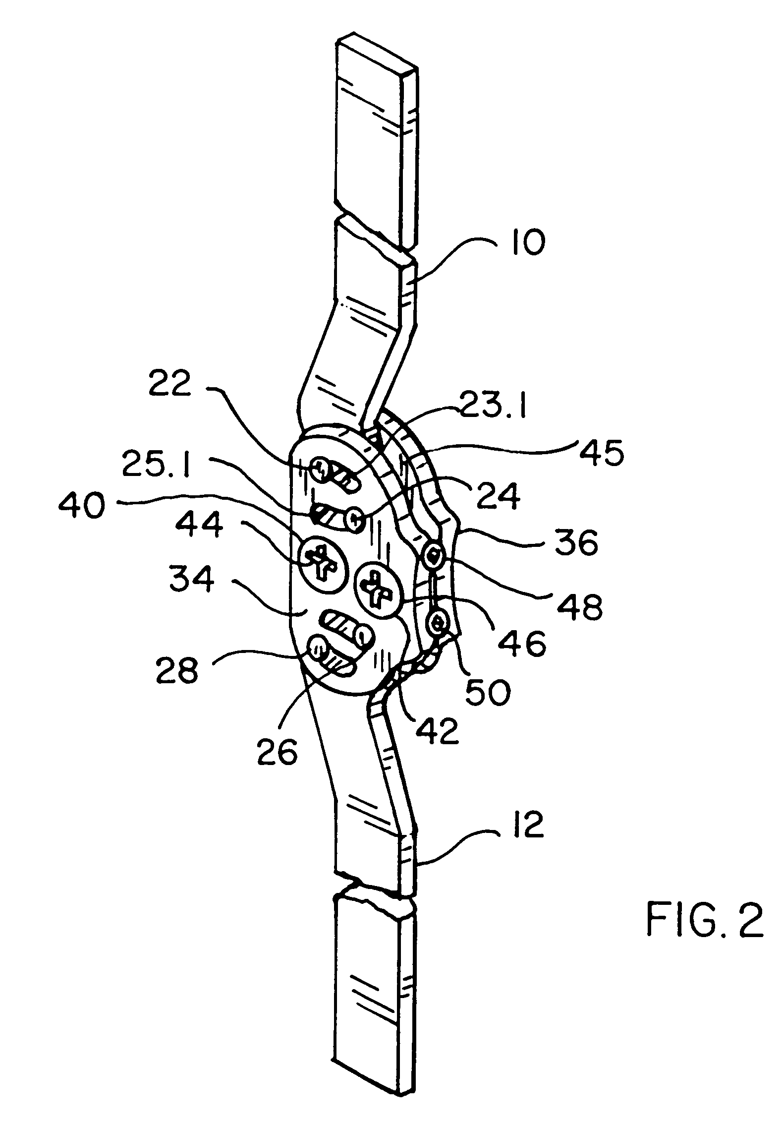
[0023]FIG. 2 is a side perspective view of the assembled multi-centric hinge orthopedic joint.

[0024]FIG. 3 is a reverse opposite side perspective view, relative to FIG. 2, of the assembled multi-centric hinge orthopedic joint of the present invention in a state of extension about a rotational axis showing a 180 degree angle between the upper and lower arms.

[0025]FIG. 4 is a side perspective view similar to that of FIG. 3 of the assembled multi-centric hinge orthopedic joint in a state of flexion about a rotational axis showing (a) a 150 degree angle between the upper and lower arms, and (b) relative direction of...


PUM


Abstract

A multi-centric orthopedic joint having inner and outer guide plates and upper and lower arms rotatably connected to the guide plates for pivotal movement therebetween. The plates each include upper and lower pairs of curved bean shaped slots, tilted relative to one another. The arms include a proximal end, the proximal end further including pins positioned and proportioned for complimental sliding movement within the upper and lower slots of the guide plates. Set screws are positioned between the inner and outer guide plate against a locking surface of the proximal end of each arm. When the set screws are loosened the upper and lower arms may be moved relative to one another, permitting the guide pins to slide within the slots but in opposite directions relative to one another. Flat-screws secure the inner and outer guide plates and co-act with the set screws as a locking mechanism of proximal ends of said arms at a desired angulation between them.

Description

CROSS REFERENCE TO RELATED APPLICATION[0001]This application claims the benefit under 35 USC 119(e) of the provisional patent application Ser. No. 60 / 936,802, filed Jun. 25, 2007, which is hereby incorporated by reference in its entirety.BACKGROUND OF THE INVENTION[0002]1. Area of the Invention[0003]The present invention relates generally to orthopedics and more particularly to a multi-centric hinge joint for use in knee braces.[0004]2. Prior Art[0005]Hinge joints that operate to support or assist injured or infirmed body limbs are known in the art. Such devices typically comprise a pair of relatively moveable support members attached respectively to different parts of the body, for example, the upper and lower leg. In addition, some form of articulation means provides a resilient or other controlled or controllable interconnection between the proximal and distal members of the support device.[0006]It is desirable for a hinge joint to provide control of an upper limb relative to a l...

Claims


Application Information

Patent Timeline
Patent Type & Authority Patents(United States)
IPC IPC(8): A61F5/00
CPCA61F5/0123A61F2005/0146A61F2005/0158A61F2005/0167
Inventor PANSIERA, TIMOTHY
Owner FILLAUER CO INC
Learn More