Bodymaker ram attachment

a bodymaker and ram technology, applied in the direction of shaping tools, forging/hammering/hammering apparatuses, forging/hammering/pressing machines, etc., can solve the problem of significant “down-time”

Active Publication Date: 2012-01-10
CROWN PACKAGING TECH
View PDF8 Cites 2 Cited by
  • Summary
  • Abstract
  • Description
  • Claims
  • Application Information

AI Technical Summary

Benefits of technology

[0007]This locking element prevents the ram from being unscrewed when loosening and tightening the bolt, which secures a punch to the opposite end of the ram.
[0008]Furthermore, this arrangement allows the clamp ring and locking element to be loosened or removed from the ram attachment without loosening locator-slide block connection, thereby maintaining alignment of registration diameter on the locator to bushing assembly

Problems solved by technology

This involves significant “down-time” (several hours) for dismantling the machine to remove the slide block and ram, as well as the time required for subsequent re-alignment of the ram when reassembling.

Method used


Image

  • Bodymaker ram attachment
  • Bodymaker ram attachment
  • Bodymaker ram attachment

Examples


Embodiment Construction

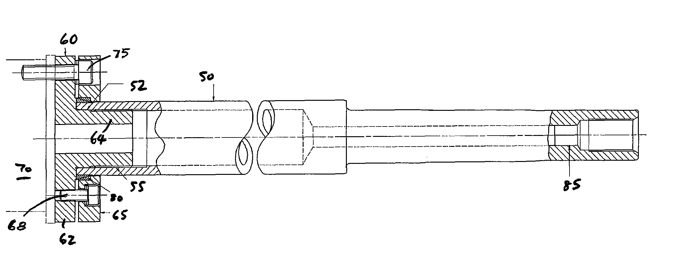
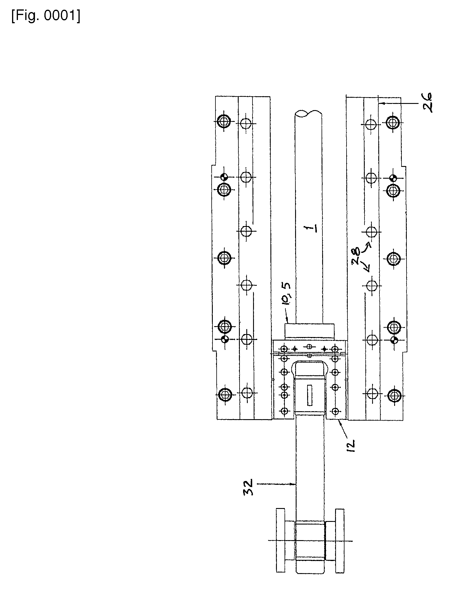
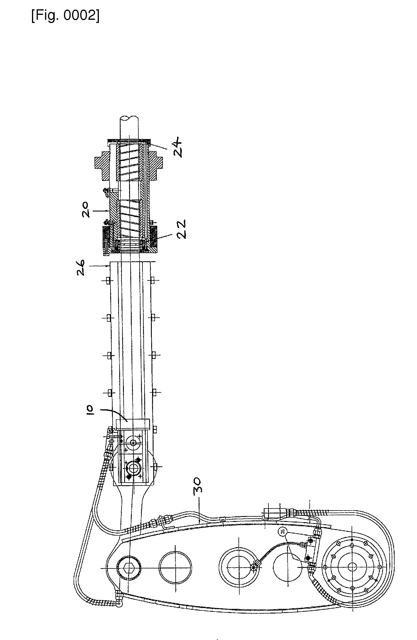
[0016]The prior art ram attachment shown in FIGS. 1 to 3 comprises clamp ring 10, which clamps a ram 1 to a slide or slide block 12 using a flange on the back of the ram. Although the flange is referred to by its reference 5, the flange of the prior art is, in fact, enclosed within the clamp ring 10 and cannot be seen when assembled. As shown in FIG. 2, the clamp ring 10 and flange 5 that secure the ram 1 to the slide block have a larger diameter than the bore of the ram bush assembly 20. In order to remove the ram seals (22, 24) the ram has to be removed backwards from the machine. The procedure used to achieve a change of the seals is outlined below.

[0017]Referring firstly to FIG. 2, the machine has to be positioned with the ram fully back (bottom dead centre) and the oil turned off. Once the oil has been turned off, the machine cannot be moved. The top slide plates 26 are then removed by removing the 12 off screws 28 then lifting the plates 26 from the machine. The 6 off ram clam...


PUM

PropertyMeasurementUnit
diameteraaaaaaaaaa
timeaaaaaaaaaa
clamping forceaaaaaaaaaa

Abstract

A bodymaker ram attachment has a screwed locator (60), which is fastened to a slide block (70) of the bodymaker and can be aligned to the machine. A new ram with an internal thread and location diameter is screwed onto the locator. A clamp ring (65) tightens a locking element (80) so as to fix the ram (50) to the locator (60) when screws (68), which fasten the clamp ring to the locator, are tightened. The advantage of this new attachment is that the ram can be removed quickly by loosening the clamp ring and locking element then unscrewing the ram from the locator. The ram can then be removed and replaced by sliding through the front of the machine without the need for further disassembly.

Description

TECHNICAL FIELD[0001]This invention relates to a bodymaker ram attachment for use in can manufacture. The invention also relates to a method of attaching a bodymaker ram to the bodymaker.BACKGROUND ART[0002]One example of bodymaker is that used for the production of thin-walled metal cans by the so-called “drawing and wall-ironing” (DWI) process. In a DWI process, a flat circular blank of metal is drawn through one or more drawing dies to form a shallow cup. The cup is then mounted on the free end of a punch which extends from a reciprocating ram, and the cup wall is then “ironed” by passing through one or more ironing dies to lengthen the side wall of the cup and form a can. Clearly it is important to the ironing process that the ram (and punch) are aligned with the bore of the dies if the ironing is to be controlled over repeated cycles.[0003]In order to drive the ram for the reciprocating action, the ram is connected to a slide block of the bodymaker. In known bodymakers, the ram...

Claims


Application Information

Patent Timeline
Patent Type & Authority Patents(United States)
IPC IPC(8): B21D37/01B21D24/16
CPCB21D22/30
Inventor WOULDS, WILLIAM
Owner CROWN PACKAGING TECH
Why Eureka
Try Eureka