Optimizing product drying through parallel lines of centrifuges and dryer process units

a technology of parallel lines and dryers, applied in adaptive control, process and machine control, instruments, etc., can solve problems such as inability to meet the requirements of product drying, equipment in parallel paths may not always be characterized by the same performance profiles and efficiency, and flow rates through parallel paths

Active Publication Date: 2012-01-24
ROCKWELL AUTOMATION TECH
View PDF81 Cites 45 Cited by
  • Summary
  • Abstract
  • Description
  • Claims
  • Application Information

AI Technical Summary

Problems solved by technology

However, when this type of expansion is implemented, plant operators may be presented with control issues regarding how to distribute flow rates through the parallel paths.
In particular, the equipment in the parallel paths may not always be characterized by the same performance profiles and efficiencies.
Therefore, simply routing proportional flow rates through the parallel paths (e.g., 20% flow rate through each of five parallel paths) may not be the most desirable control scheme.

Method used


Image

  • Optimizing product drying through parallel lines of centrifuges and dryer process units
  • Optimizing product drying through parallel lines of centrifuges and dryer process units
  • Optimizing product drying through parallel lines of centrifuges and dryer process units

Examples


Embodiment Construction

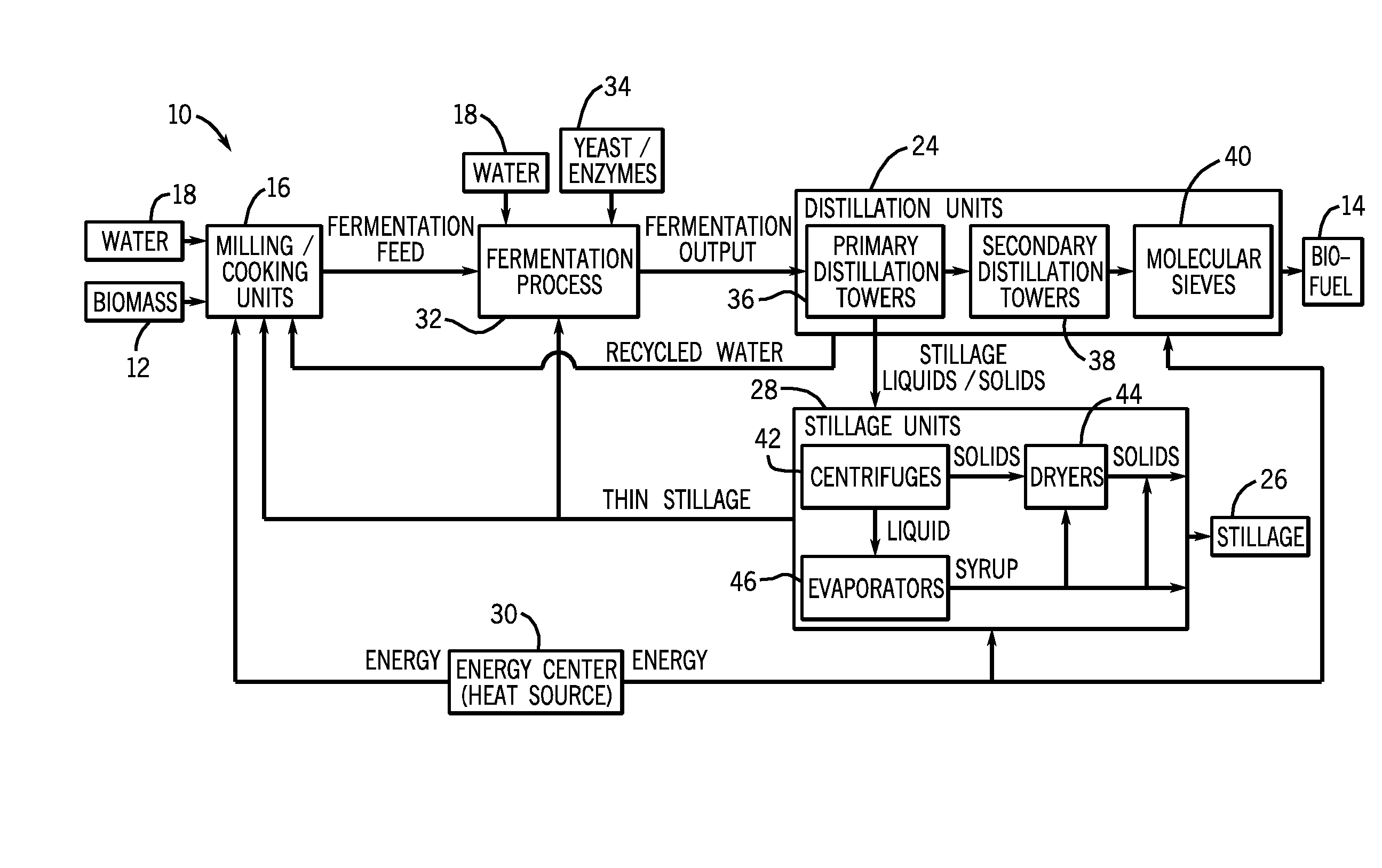
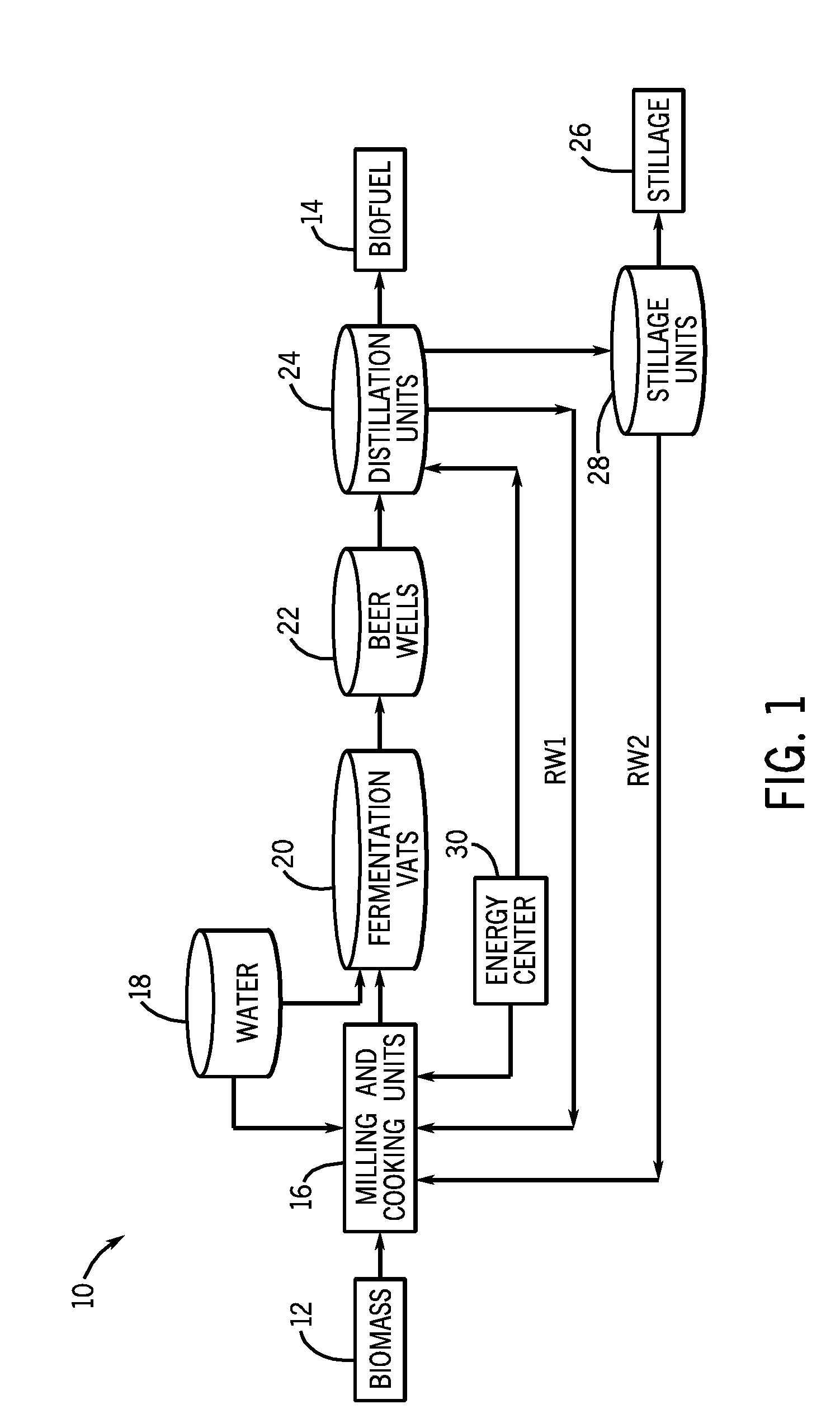
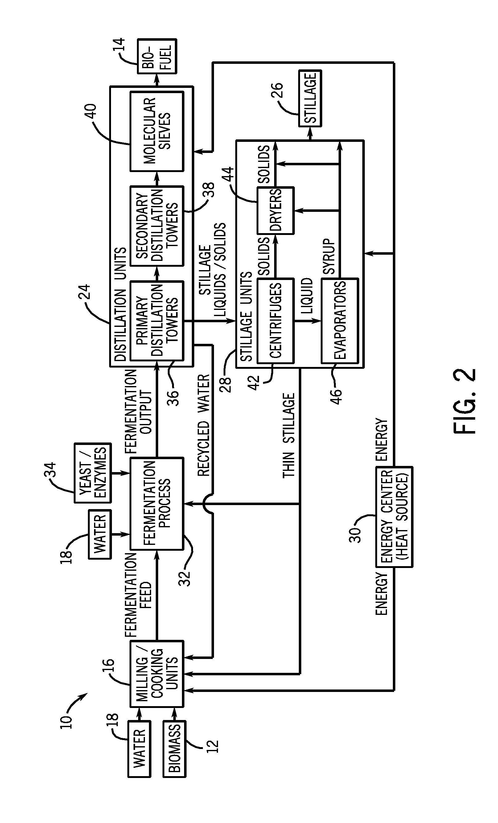
[0012]Turning now to the drawings, FIG. 1 is a diagram of an exemplary biofuel production plant 10, illustrating how biomass 12 may be processed through several stages to produce biofuel 14. Biomass 12 may first be provided to a milling and cooking process, e.g., milling and cooking units 16, where water 18 (and possibly recycled water RW1 and RW2) may be added and the biomass 12 may be broken down to increase the surface area-to-volume ratio. This increase in surface area may allow for sufficient interaction of the water 18 and biomass 12 surface area to achieve a solution of fermentable sugars in water 18. The mixture, a biomass 12 and water 18 slurry, may be cooked to promote an increase in the amount of contact between the biomass 12 and water 18 in solution and to increase the separation of carbohydrate biomass from non-carbohydrate biomass. The output of the milling and cooking units 16 (i.e., the fermentation feed or mash) may then be sent to a fermentation process, where one...


PUM

PropertyMeasurementUnit
surface area-to-volume ratioaaaaaaaaaa
flow ratesaaaaaaaaaa
flow rateaaaaaaaaaa

Abstract

The present invention provides novel techniques for controlling flow rates through parallel distribution paths of centrifuges and dryers using model predictive control. In particular, the present techniques are presented in the context of biofuel production, wherein control of whole stillage flow rates through parallel distribution paths of centrifuges and dryers may be optimized. However, the present techniques may also be applied to other suitable applications, such as the production of agricultural products, where parallel distribution paths of centrifuges and dryers may be used to separate solids from liquids as well as to remove water from the solids and liquids.

Description

BACKGROUND[0001]The present invention relates generally to control systems, and more particularly to model predictive control employing novel techniques for optimizing drying processes, such as the drying of biofuel stillage products between parallel paths.[0002]Many processing plants, such as biofuel production plants, include separation and drying processes which may use centrifuges, dryers, evaporators, and so forth. These processes may separate solids from liquids as well as remove water from the solid and liquid products. As these plants expand, multiple parallel paths for the separation and drying processes may be used. This type of expansion may allow for increased throughput. In addition, this expansion may be integrated into the current plant to allow for flexibility in operating paths. This cross-integration in plant expansions is not uncommon as this provides the plant operating flexibility and the ability to shut sections of the plant down without shutting the entire pla...

Claims


Application Information

Patent Timeline
Patent Type & Authority Patents(United States)
IPC IPC(8): G05D11/00G05D11/02G05B21/00C12P7/08
CPCB01D3/42C12P7/06G05B13/047G06Q50/06B01D21/26Y02E50/17Y02E50/10
Inventor MACHARIA, MAINA A.MAXWELL, DONALD MELVINBUDARAJU, SRINIVAS
Owner ROCKWELL AUTOMATION TECH
Why Eureka
Try Eureka