
Network operations management method and apparatus

a network operation and management method technology, applied in the field of network operations management methods and apparatuses, can solve the problems of insufficient improvement of efficiency, total power consumption of data center dc, and difficulty in further saving power by reallocating virtual servers, and achieve the effect of efficient power saving

Inactive Publication Date: 2012-01-24
KDDI CORP
View PDF4 Cites 2 Cited by
  • Summary
  • Abstract
  • Description
  • Claims
  • Application Information

AI Technical Summary

Benefits of technology

[0021]An object of the present invention is to provide a network operations management method and apparatus which realizes efficient power-saving by enabling virtual servers to move between physical servers beyond network segments.
[0023]According to the present invention, in conjunction with a dynamic change of physical servers on which virtual servers are operated according to the use of the virtual servers, the network segment of the physical server to which the virtual servers move can be logically changed, so that the virtual servers become movable between the physical servers beyond the network segments. Therefore, by allocating the virtual servers preferentially to physical servers which share air-conditioning equipment and lighting facilities or preferentially allocating the virtual servers to the physical servers connected to a common network device, efficient power-saving is realized.

Problems solved by technology

In the above-described conventional technique, a virtual server cannot be moved between physical servers in different network segments (that is, in different resource pools), so that it is difficult to sufficiently improve the efficiency.
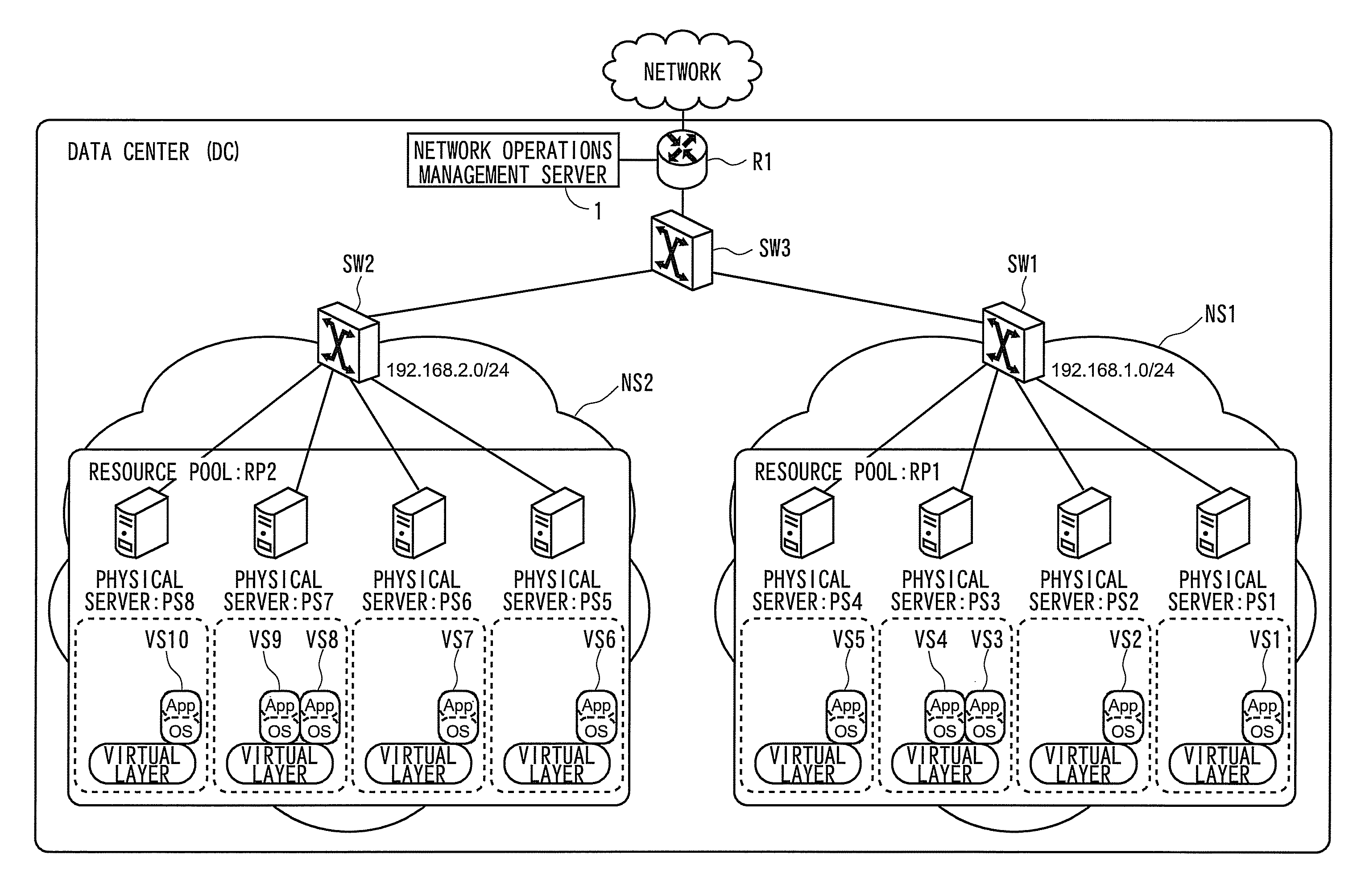
However, the total power consumption of the data center DC greatly depends on the power consumption of air-conditioning equipment, lighting facilities, and switches SW for switching the lines of the physical servers as well as the power consumption of the physical servers.
However, with the above-described conventional technique, grouping of the physical servers bundled in the respective resource pools cannot be dynamically changed, so that it is difficult to further save power by reallocating the virtual servers between physical servers beyond the network segments as described in FIG. 11.

Method used


Image

  • Network operations management method and apparatus
  • Network operations management method and apparatus
  • Network operations management method and apparatus

Examples


Embodiment Construction

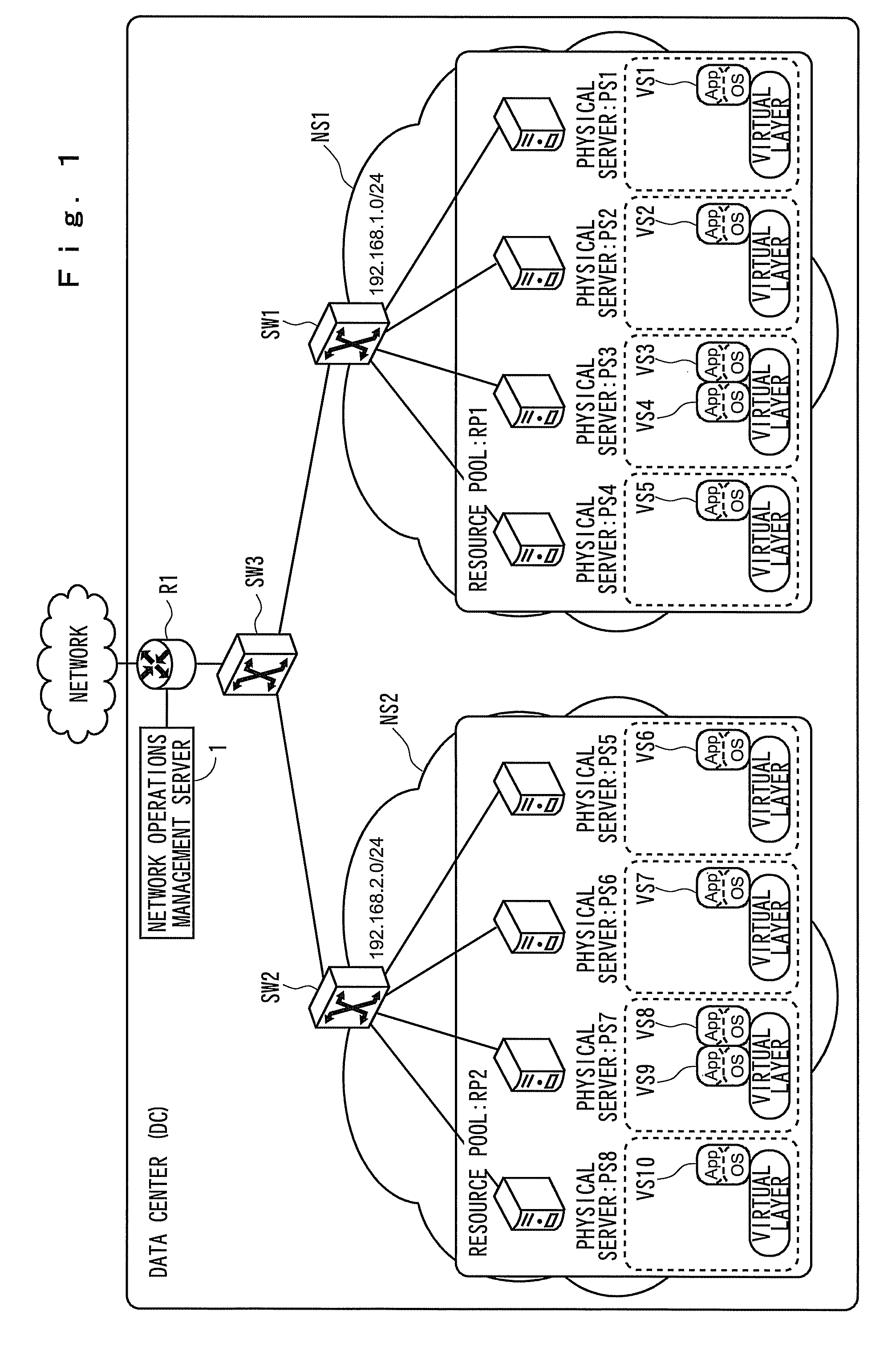
[0035]FIG. 1 is a block diagram showing a configuration of a network to which a network operations management method of the present invention is applied, and in a data center DC, two network segments NS1 (192.168.1.0 / 24) and NS2 (192.168.2.0 / 24) connected via a router R1 and switches SW1, SW2, and SW3 exist. To the router R1, a network (NW) operations management apparatus (server) 1 of the present invention is connected.

[0036]In the present embodiment, the router R1 and the switches SW1, SW2, and SW3 support the VLAN (Virtual LAN) function to make it possible to logically change the network segment of physical servers as a destination to which virtual servers move without a physical connection change by separating a physical connection configuration and a logical connection configuration of the network in response to an instruction from the NW operations management server 1.

[0037]In FIG. 1, in the first resource pool RP1 of the first network segment NS1, four physical servers PS1, P...


PUM


Abstract

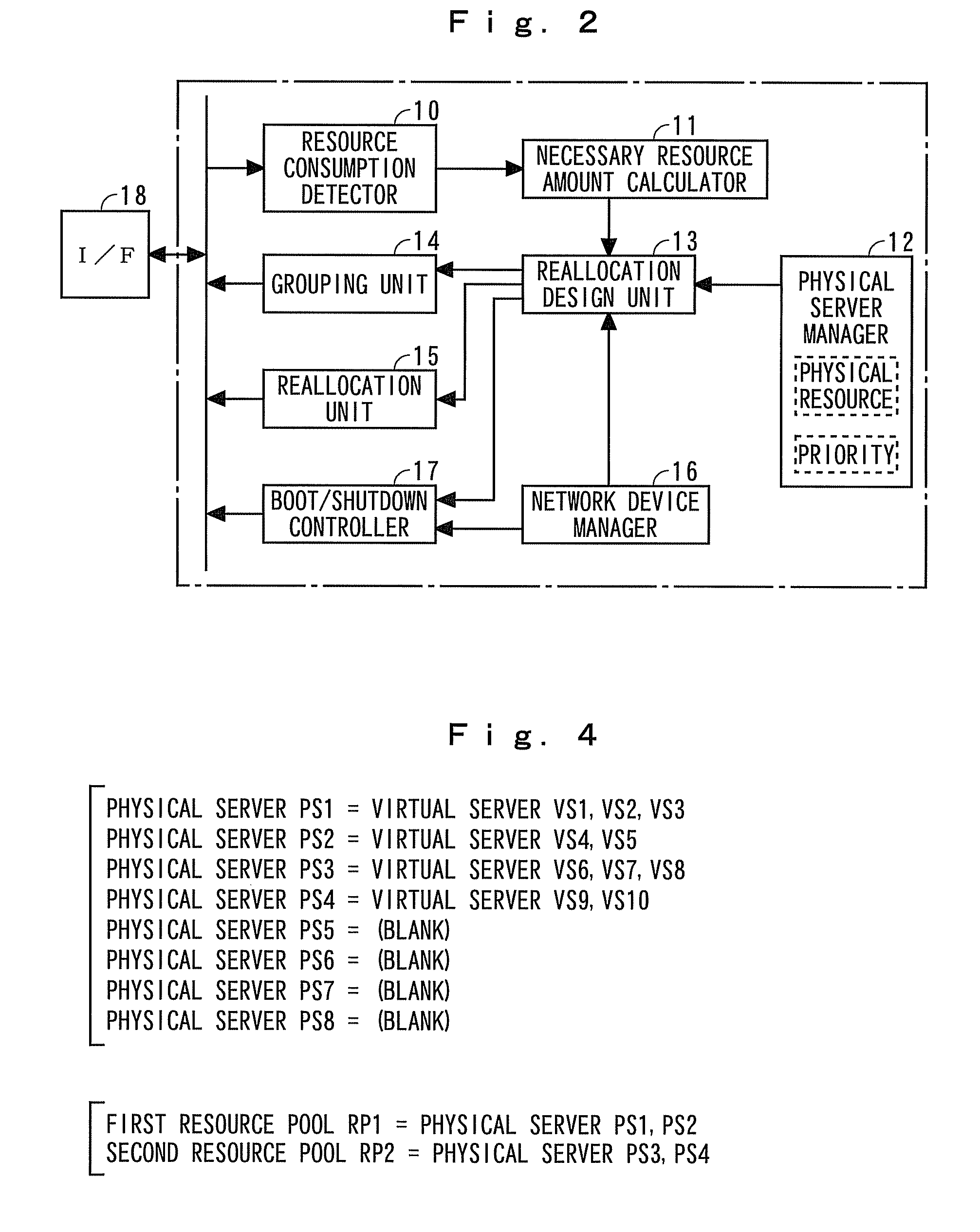
The present invention provides a network operations management method and apparatus which realizes efficient power-saving by enabling virtual servers to move between physical servers beyond network segments. A reallocation design unit 13 designs reallocation of virtual servers to physical servers so that necessary resource amounts are assigned to all virtual servers. When virtual servers VS need to move between physical servers PS beyond network segments NS for the designed reallocation, a grouping unit 14 changes a network segment NS to which physical servers PS are connected by changing the configuration of a router and switches. A reallocation unit 15 realizes efficient power-saving by reallocating the virtual servers to the physical servers based on the design made by the reallocation design unit 13.

Description

[0001]The present application is claims priority of Japanese Patent Application Serial No. 2008-185995, filed Jul. 17, 2008, the content of which is hereby incorporated by reference in its entirety.BACKGROUND OF THE INVENTION[0002]1. Field of the Invention[0003]The present invention relates to a network operations management method and apparatus which operates each of a plurality of physical servers logically as at least one virtual server and dynamically changes virtual servers to be allocated to the respective physical servers by moving the virtual server between the physical servers.[0004]2. Description of the Related Art[0005]A virtualization technique for effectively utilizing computer resources (physical resources) of a plurality of physical servers by operating each of the physical servers logically as at least one server (virtual server) is known.[0006]Non-patent documents 1 and 2 disclose techniques for improving the efficiency of the operations of network devices and serve...

Claims


Application Information

Patent Timeline
Patent Type & Authority Patents(United States)
IPC IPC(8): G06F15/173
CPCG06F9/5077Y02D10/00
Inventor ARAI, DAISUKEYOSHIHARA, KIYOHITOIDOUE, AKIRA
Owner KDDI CORP
Learn More