Flow sensing device including a tapered flow channel

a flow sensing device and flow channel technology, applied in measurement devices, volume/mass flow measurement, instruments, etc., can solve the problems of turbulence in flow effects and flow eddies in flow channels, extra design or set-up time, and extra cost, so as to reduce flow eddies, enhance flow stability, and reduce flow eddies

Active Publication Date: 2012-01-31
HONEYWELL INT INC
View PDF117 Cites 19 Cited by
  • Summary
  • Abstract
  • Description
  • Claims
  • Application Information

AI Technical Summary

Benefits of technology

[0008]It is another aspect of the present invention to provide a fluid flow sensor with an improved flow channel that can reduce or prevent unwanted flow eddies from forming within fluid flowing through the flow path leading to a sensor.
[0009]The aforementioned aspects and other objectives and advantages can now be achieved as described herein. A flow sensing device comprises a main flow channel defining a fluid (e.g., gas or liquid) flow path, through which a fluid flows. An upstream flow channel and a downstream flow channel can be molded into the main flow channel, with a sensor region bypassing the flow path of the main flow channel. A fluid flow sensor can be placed between the upstream flow channel and the downstream flow channel for measuring a flow rate of the fluid in the flow channel. In the present invention, the upstream flow channel is tapered in a direction toward the airflow sensor. The downstream flow channel can also be tapered. Tapered upstream and downstream flow channels reduce flow eddies across the flow sensor, and thereby enhancing flow stability and stabilizing a sensor output signal, which leads to optimal sensing performance of the flow sensor.
[0010]In accordance with another feature of the present invention, at least one tapered flow channel formed into a main flow channel defining a flow tube as an alternate fluid flow path, wherein said at least one tapered flow channel bypasses some fluid flow from the main flow channel into said alternate fluid flow path. A flow sensor disposed within said alternate fluid flow path, wherein said tapered flow channel is tapered in a direction of fluid flow toward said flow sensor to thereby reduce flow eddies and enables optimal sensing performance by said flow sensor.
[0011]Furthermore, the sensing device can also include a set of narrow flow restrictors, which can be arranged within the main flow channel in order to limit the flow rate of the fluid across the flow sensor by limiting flow in the main flow channel and the flow tube and / or alternate flow path. The main flow channel can preferably exhibit a cross-sectional shape and size compatible with flow systems. The upstream and downstream flow channels, or alternate flow path, can be tapered by increasing a height at a flow inlet and reducing it when the upstream and downstream flow channels approach towards the airflow sensor. Therefore, the flow velocity of the fluid can be more stable when the fluid flow changes direction from the main flow channel into the upstream flow channel. Hence, the sensing device can produce uniform flow of the fluid across the airflow sensor for more accurate flow measurements.

Problems solved by technology

These upstream and downstream sides of the flow channel can create a difference in pressure and flow velocity of the fluid across the flow sensors, which leads to turbulent flow effects and flow eddies in the flow channel.
The flow eddies can create instability in the fluid flow, which results in unstable output by the flow sensors.
Such approach requires extra precision can lead to extra design or set up time, and thus extra expensive, during the manufacturing of the flow sensors.
Additionally, the flow channel may not produce uniform, laminarizing flow of the fluid due to non-uniformities in a cross-sectional area and position of the upstream and downstream channels in the flow channel.

Method used


Image

  • Flow sensing device including a tapered flow channel
  • Flow sensing device including a tapered flow channel
  • Flow sensing device including a tapered flow channel

Examples


Embodiment Construction

[0017]The particular values and configurations discussed in these non-limiting examples can be varied and are cited merely to illustrate at least one embodiment and are not intended to limit the scope thereof. Note that in FIGS. 1-5 identical parts or elements are generally indicated by identical reference numerals.

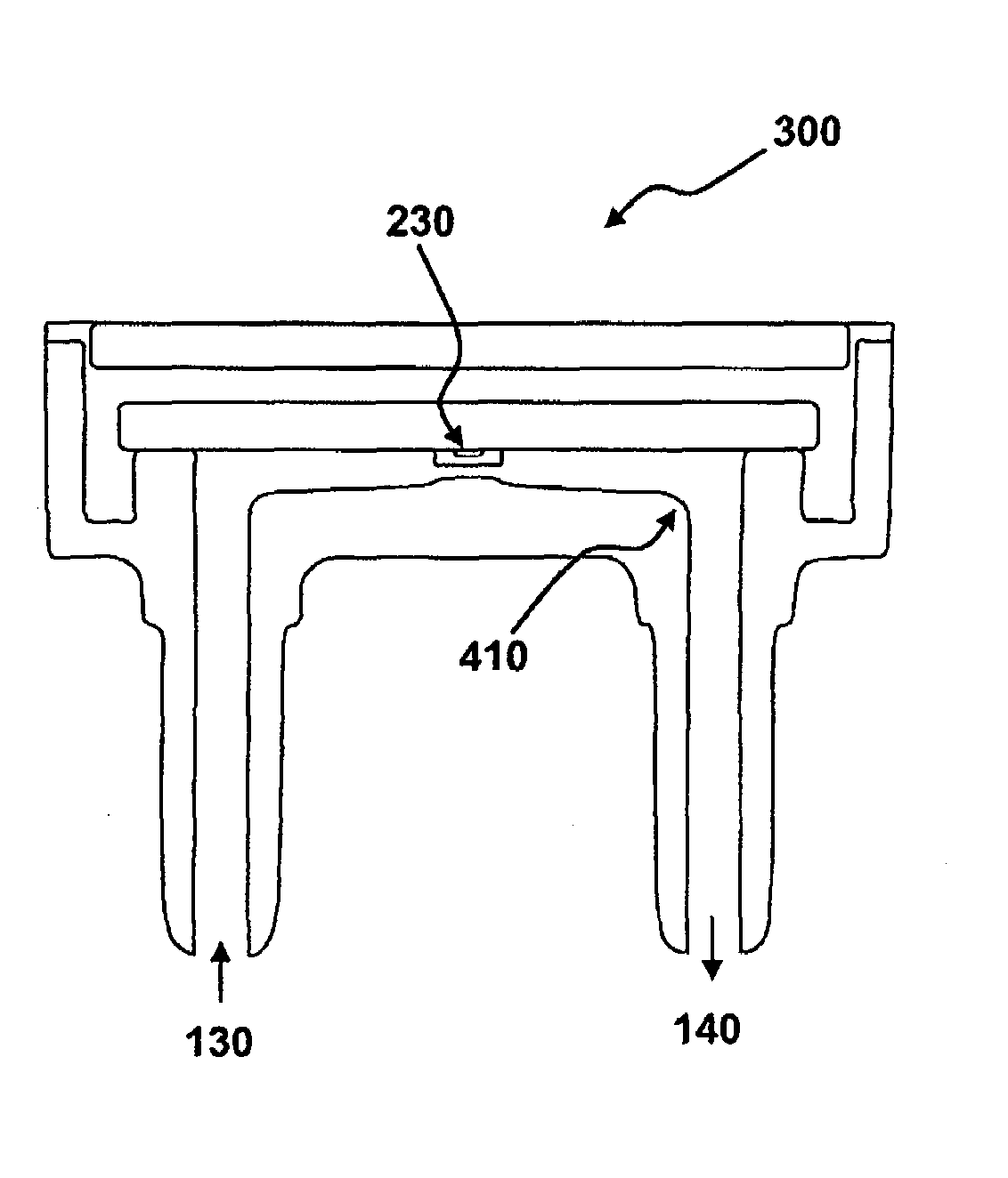
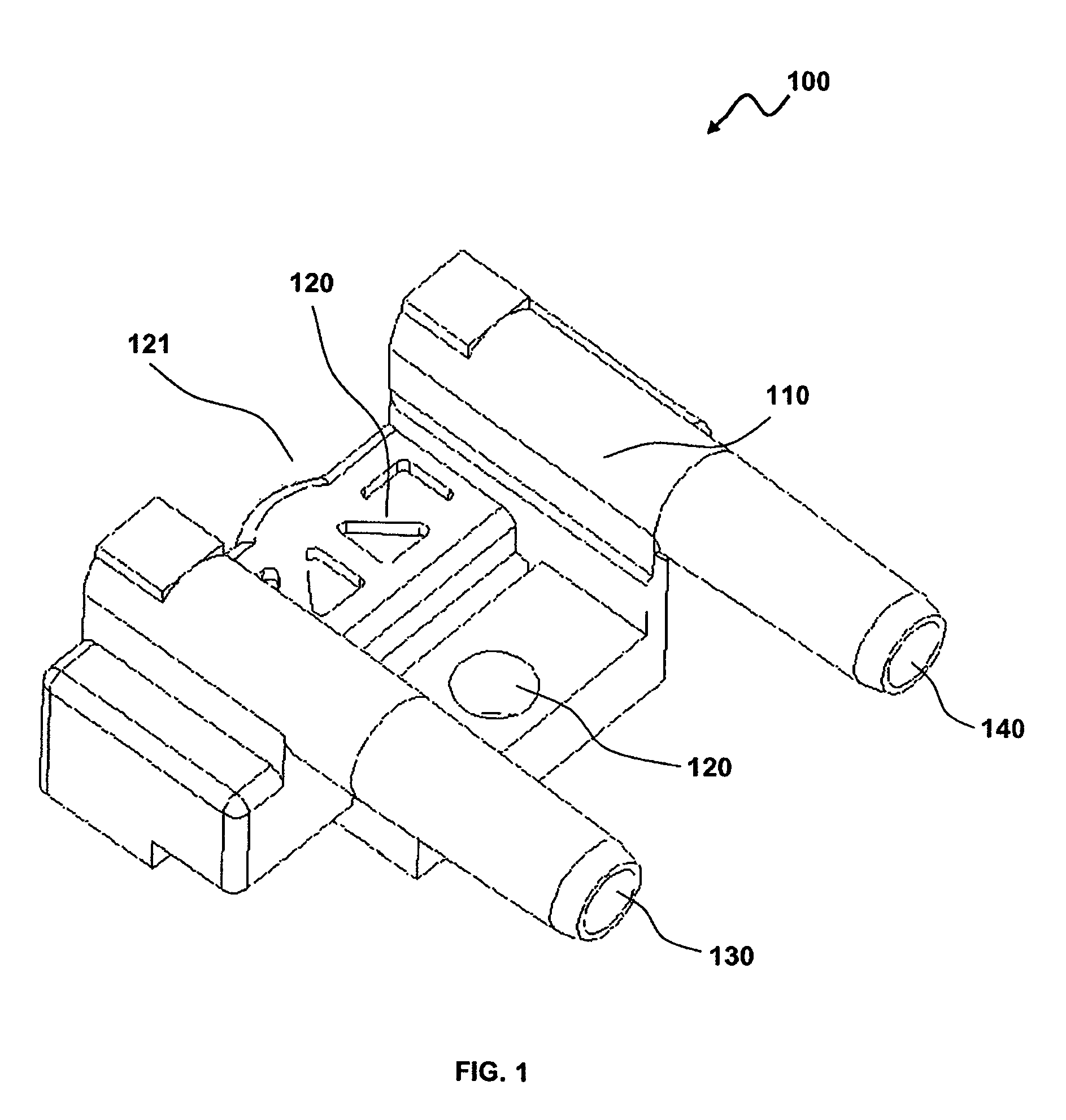
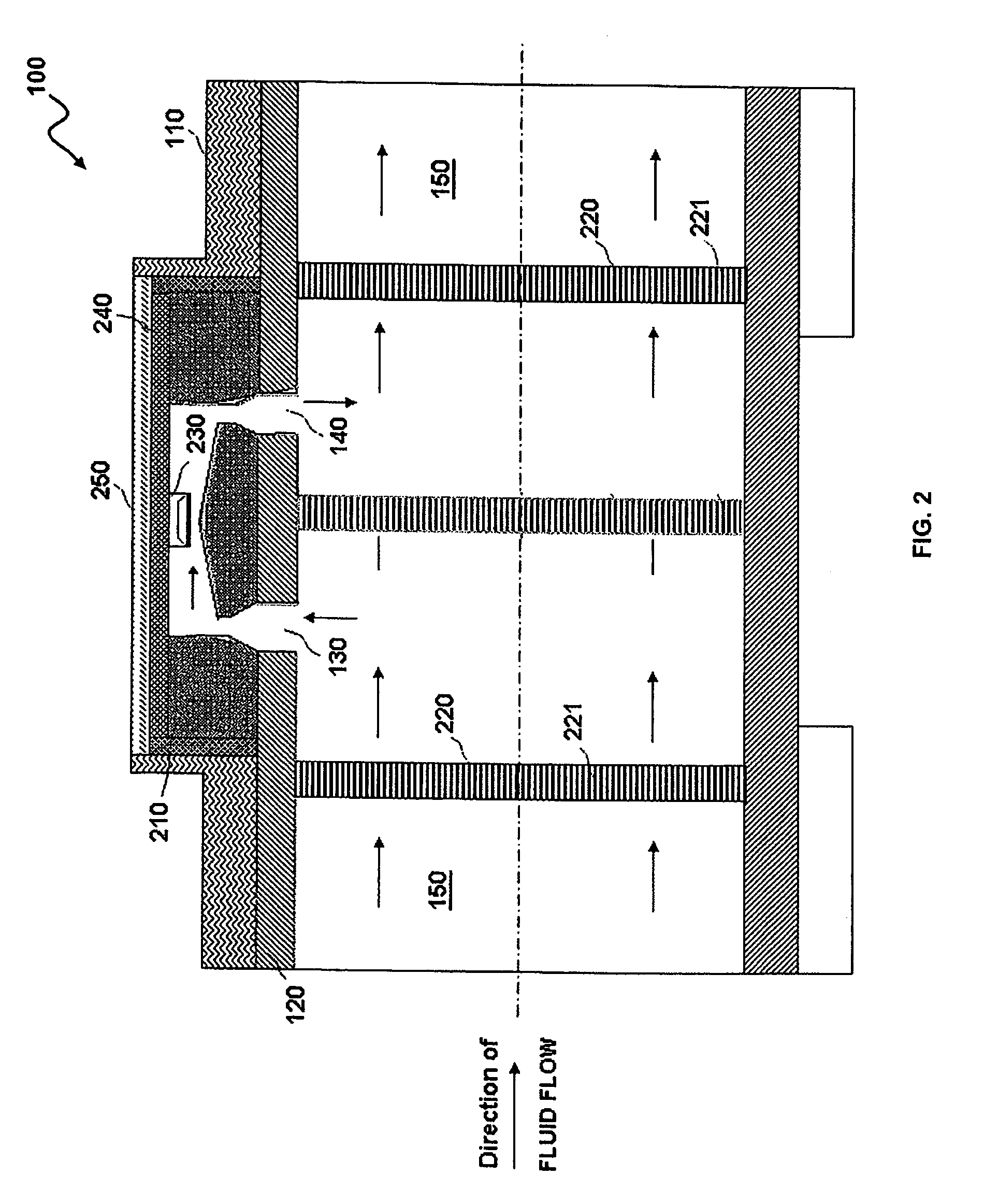
[0018]Referring to FIG. 1, a general perspective view of a flow sensing device 100 is illustrated, which can be adapted for use in implementing a preferred embodiment. The flow sensing device 100 can be disposed in a flow path 121 defined by a main flow channel 120, so that a fluid 150, as illustrated in FIG. 2, can enter and exit the main flow channel 120. Note that as utilized herein the term “fluid” can refer to a gas or a liquid. Thus, the flow sensing device 100 disclosed herein can be utilized in a flow system (not shown) for measuring a flow rate of the fluid (e.g., air or gas) flow 150. Note that the embodiments discussed herein generally relate to an airflow sens...


PUM


Abstract

A fluid flow sensing device can include a tapered fluid flow channel formed into a main channel defining a fluid flow tube as an alternate fluid flow path. A tapered fluid flow channel can bypass some fluid flow from the main fluid flow channel into the alternate fluid flow path and a flow sensor disposed within the alternate fluid flow path. The tapered flow channel is tapered in a direction of fluid flow toward the flow sensor to thereby reduce flow eddies and enable optimal sensing performance by fluid flow sensor. An upstream fluid flow channel and a downstream fluid flow channel can be molded into the main fluid flow channel, especially bypassed in the fluid flow path of the main fluid flow channel. A fluid flow sensor can be placed between the upstream fluid flow channel and the downstream fluid flow channel for measuring fluid flow rate the channel.

Description

TECHNICAL FIELD[0001]Embodiments are generally related to flow sensing devices and methods. Embodiments are also related to airflow sensors. Embodiments are additionally related to an improved flow channel for controlling flow eddies.BACKGROUND OF THE INVENTION[0002]Several flow systems utilizes fluid flow rate control mechanisms for controlling the amount of fluid, which may be in gaseous (e.g., air) or liquid form passing through a flow channel. Flow control mechanisms might also be utilized to regulate flow rates in systems such as ventilators and respirators for maintaining a sufficient flow of breathable air or providing sufficient anesthetizing gas to a patient in preparation for surgery. Typically, flow rate control occurs through the utilization of control circuitry responsive to measurements obtained from fluid flow sensors. Such flow sensors can apparently measure the flow rate of the fluid by sampling the fluid along the wall of the flow channel.[0003]In one implementatio...

Claims


Application Information

Patent Timeline
Patent Type & Authority Patents(United States)
IPC IPC(8): G01F1/68
CPCG01F1/6842G01F1/6845G01F1/72G01F5/00
Inventor SPELDRICH, JAMIE
Owner HONEYWELL INT INC
Why Eureka
Try Eureka