Cooling fan control

a cooling fan and control technology, applied in the direction of positive displacement liquid engines, pumping, machines/engines, etc., can solve the problems of increasing cooling drag, reducing the resistance of the cooling system, and adding aerodynamic drag to the front-end air flow of the vehicle, so as to achieve the effect of adding aerodynamic drag

Active Publication Date: 2012-01-31
FORD GLOBAL TECH LLC
View PDF13 Cites 18 Cited by
  • Summary
  • Abstract
  • Description
  • Claims
  • Application Information

AI Technical Summary

Benefits of technology

[0002]Vehicle cooling systems may include various cooling components such as heat exchangers, radiators, cooling fans and blowers, condensers, liquid coolant, etc. Additionally, the cooling system may receive cooling intake air from a front end of the vehicle, for example, through a vehicle or bumper opening, to assist in cooling the engine, transmission, and other components of the under-hood region. Such front-end air flow may add aerodynamic drag when the vehicle is in motion.
[0003]Various approaches may be used to reduce vehicular aerodynamic drag. One example approach is illustrated by Harich et al. in US 2008 / 0257286A1. Herein, the opening of one or more shutters and pivotable flaps in the frame of a vehicle cooling system may be adjusted, based on engine operating conditions, to thereby alter a total front end air-mass flow. Specifically, by adjusting the flaps and shutters of a variable geometry intake frame based on engine cooling demands, a cooling air flow through a blower and / or a coolant cooler may be adjusted. By restricting the shutters and / or flaps, for example, during conditions of low external air temperatures, air-flow and related aerodynamic drag may be reduced.
[0004]However, the inventors herein have recognized potential issues with such an approach. In one example, when the vehicle is moving, despite shutter and flap adjustments, some air may enter through the front end of the vehicle and rotate the blades of an unpowered fan of the cooling system. The free-wheeling fan may thereby lower cooling system resistance relative to a stationary fan which is not free-wheeling. The increase in cooling airflow thus generated when no cooling airflow is otherwise desired may lead to an increased cooling drag. As such, this may augment vehicular aerodynamic drag, thereby reducing vehicle performance and fuel economy.
[0007]For example, the braking torque may be selectively applied during a condition where the vehicle speed is above a minimum speed and the coolant temperature is below a lower threshold. Herein, the lower coolant temperature may not necessitate airflow assistance from the cooling fan. However, the rotation of the free-wheeling fan, while the vehicle is moving at the higher speed, may increase drag on the moving vehicle and reduce fuel economy. The drag may also reduce vehicle performance. Thus, during such a condition, a braking torque may be applied on the fan to reduce fan rotation (for example, reduce to a minimum speed or reduce to a halt). By selectively stopping or reducing fan rotation, air flow through the fan may be reduced when possible, thereby reducing the related aerodynamic drag. In one example, applying a braking torque may include shorting the power feed of an electric fan's motor so that the back EMF generated by the motor attached to the free-wheeling fan provides the braking torque. In another example, the braking torque may be applied mechanically, for example, using a latch or pin. Further, the braking torque may be adjusted based on vehicle operating conditions.
[0008]In this way, by selectively reducing free-wheeling of a cooling fan in a moving vehicle, based on operating conditions, cooling airflow across the fan may be reduced under selected conditions, thereby reducing cooling drag when such airflow is not otherwise needed. By reducing cooling aerodynamic drag when possible, vehicle fuel economy may be improved.

Problems solved by technology

Such front-end air flow may add aerodynamic drag when the vehicle is in motion.
However, the inventors herein have recognized potential issues with such an approach.
The free-wheeling fan may thereby lower cooling system resistance relative to a stationary fan which is not free-wheeling.
The increase in cooling airflow thus generated when no cooling airflow is otherwise desired may lead to an increased cooling drag.
As such, this may augment vehicular aerodynamic drag, thereby reducing vehicle performance and fuel economy.
As such, the fan may be “free-wheeling”, that is, the fan may be rotating due to the flow of ram air through the fan blades, and may not be driven by the engine.
Herein, the lower coolant temperature may not necessitate airflow assistance from the cooling fan.
However, the rotation of the free-wheeling fan, while the vehicle is moving at the higher speed, may increase drag on the moving vehicle and reduce fuel economy.
The drag may also reduce vehicle performance.

Method used


Image

  • Cooling fan control
  • Cooling fan control
  • Cooling fan control

Examples


Embodiment Construction

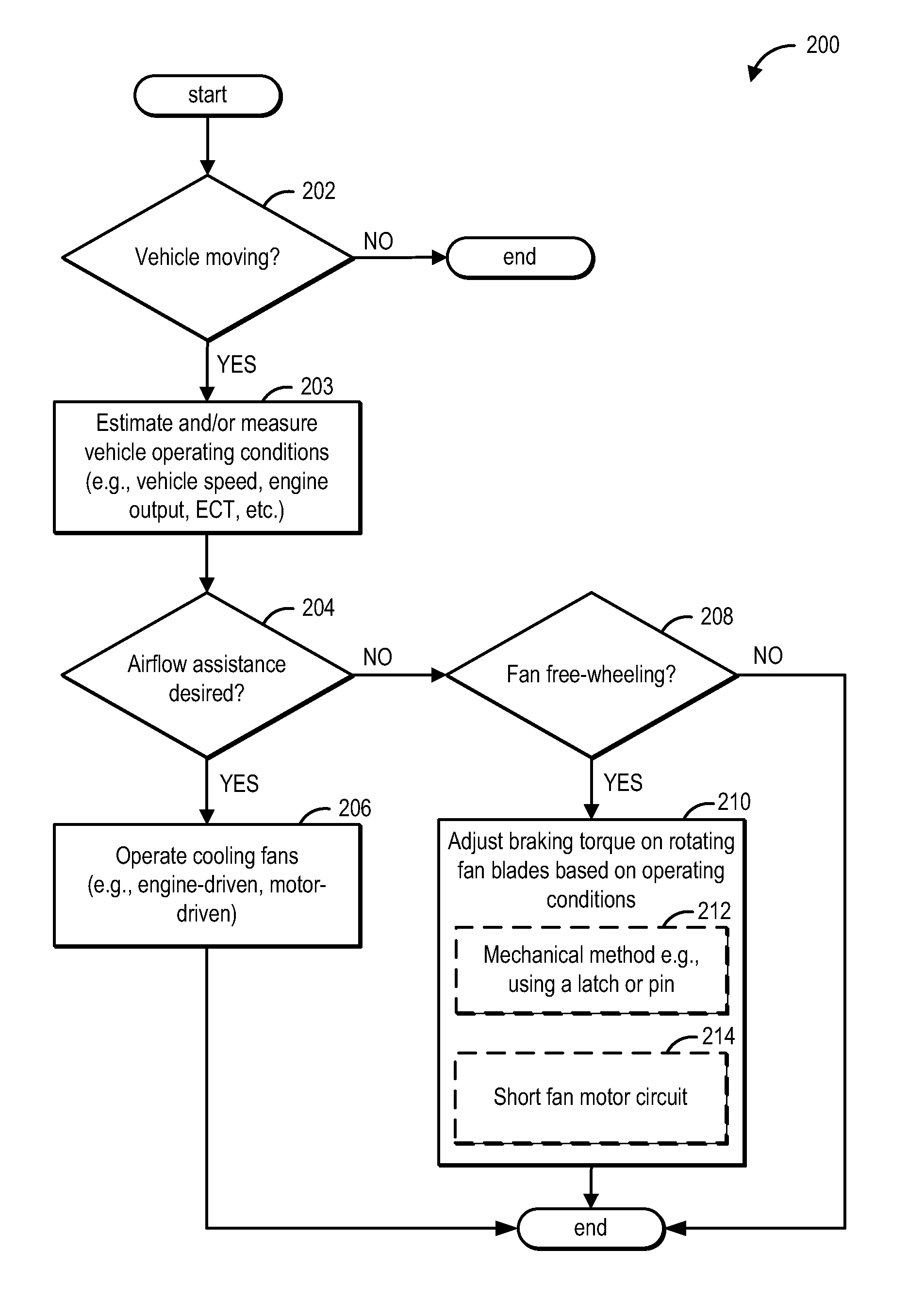
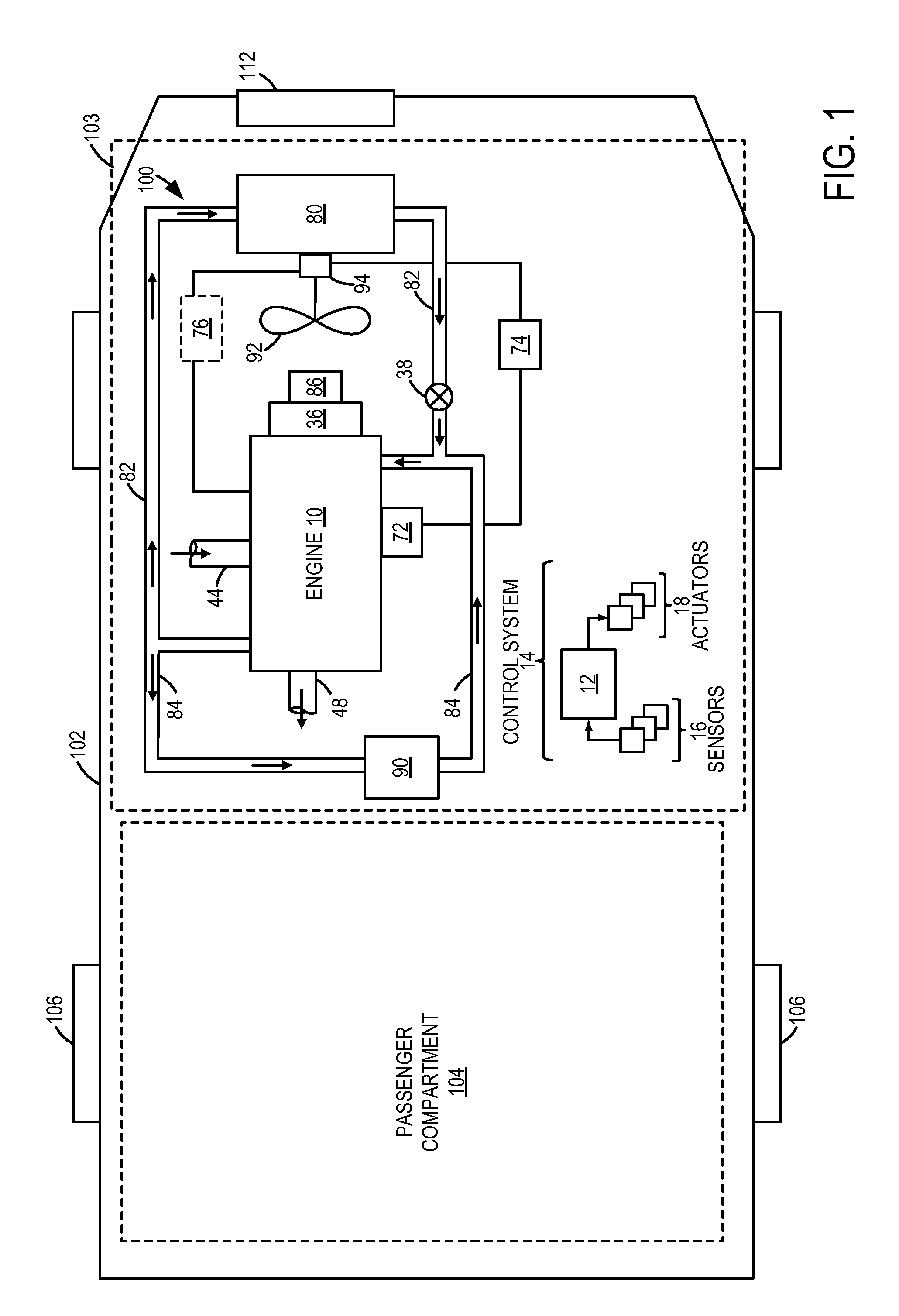
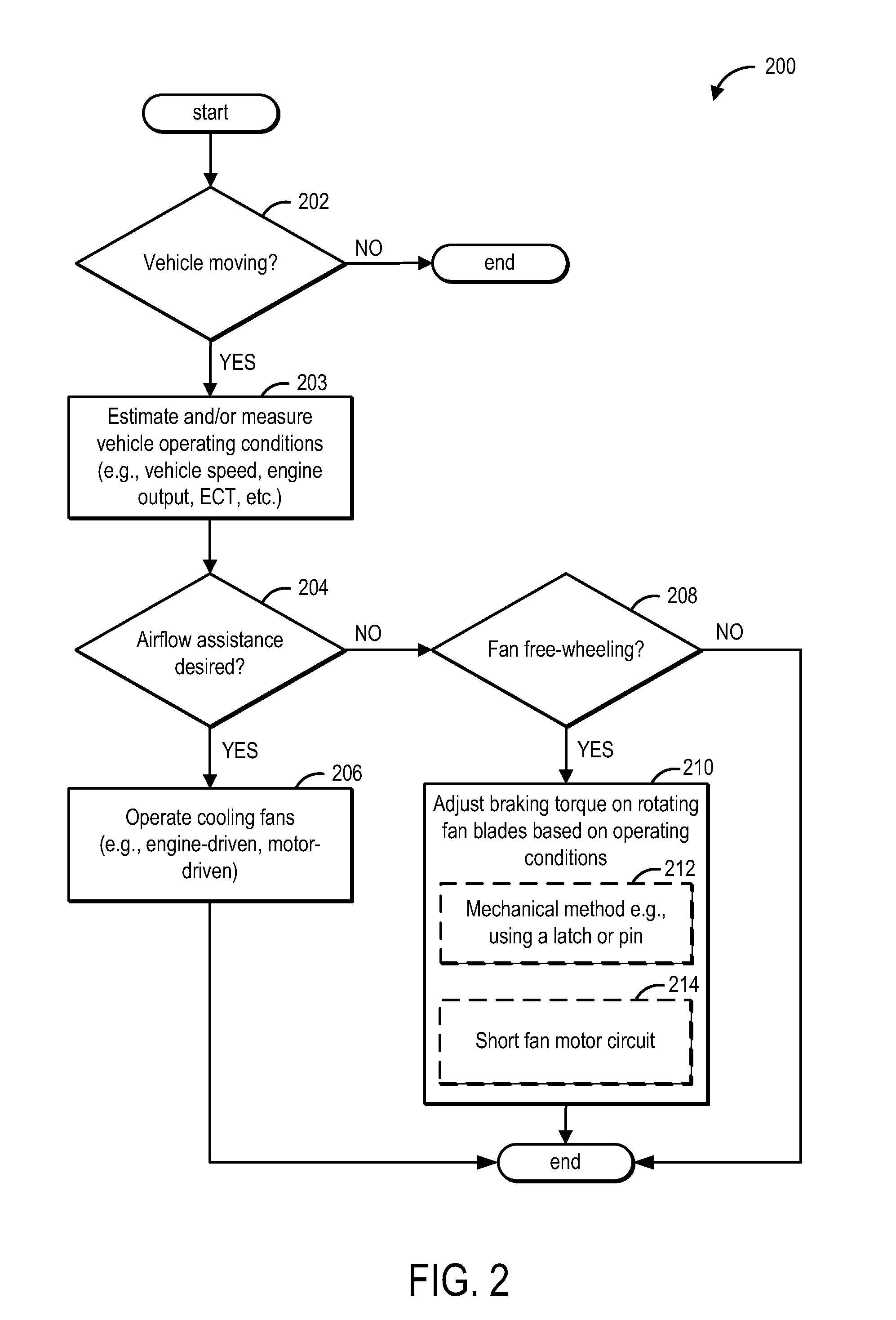
[0013]The following description relates to systems and methods for controlling a cooling fan in a vehicle cooling system, such as the system of FIG. 1. During engine operation, the cooling fan may be driven by the engine to flow cool air through the front end of a vehicle and cool components in the under-hood region. To reduce cooling drag induced by free-wheeling of the fan, during a vehicle moving condition when airflow assistance is not required, based on vehicle operating conditions, a braking torque may be selectively applied to the rotating fan blades to reduce airflow through the fan and under-hood region. An engine controller may perform a control routine, such as depicted in FIG. 2, to either apply a mechanical braking torque or an electrical braking torque, based on the vehicle operating conditions, to thereby stop fan rotation. By reducing fan free-wheeling, air flow through the vehicle cooling system may be reduced when fan operation is not desired. By reducing front-end...


PUM


Abstract

Methods and systems are provided for reducing aerodynamic drag on a moving vehicle. One example method comprises, during a first vehicle moving condition, operating the cooling fan, and during a second vehicle moving condition, selectively applying a braking torque on the fan.

Description

FIELD[0001]The present description relates to methods and system for controlling a cooling fan of a vehicle cooling system.BACKGROUND AND SUMMARY[0002]Vehicle cooling systems may include various cooling components such as heat exchangers, radiators, cooling fans and blowers, condensers, liquid coolant, etc. Additionally, the cooling system may receive cooling intake air from a front end of the vehicle, for example, through a vehicle or bumper opening, to assist in cooling the engine, transmission, and other components of the under-hood region. Such front-end air flow may add aerodynamic drag when the vehicle is in motion.[0003]Various approaches may be used to reduce vehicular aerodynamic drag. One example approach is illustrated by Harich et al. in US 2008 / 0257286A1. Herein, the opening of one or more shutters and pivotable flaps in the frame of a vehicle cooling system may be adjusted, based on engine operating conditions, to thereby alter a total front end air-mass flow. Specific...

Claims


Application Information

Patent Timeline
Patent Type & Authority Patents(United States)
IPC IPC(8): F01P7/02
CPCF01P7/046F01P7/048
Inventor SCHWARTZ, WILLIAM SAMUELGALE, ALLAN ROYKARANTH, DINAKARAPARKS, STEVEN JAMESO'DONOHUE, GARRETT
Owner FORD GLOBAL TECH LLC
Why Eureka
Try Eureka