Endoscopic system and method for therapeutic applications and obtaining 3-dimensional human vision simulated imaging with real dynamic convergence

a technology of endoscopic system and simulated imaging, applied in the field of endoscopic system and method for therapeutic applications, can solve the problems of limited depth perception of users and lack of 3-dimensional imaging

Active Publication Date: 2012-01-31
ABOU EL KHEIR TAREK AHMED NABIL
View PDF165 Cites 81 Cited by
  • Summary
  • Abstract
  • Description
  • Claims
  • Application Information

AI Technical Summary

Benefits of technology

[0008]Thus, as the diagnostic / sensor or therapeutic devices at the distal end of the main tubular shaft are inserted along with it into a cavity (and precede it into the cavity), such as an abdominal cavity having a endoscopic port, the shaft and sensors slide easily through the endoscopic port but the adjustment ring is stopped from entering the cavity by the endoscopic port's external structure. Continued forward movement of the main tubular shaft into the cavity toward a target object after the adjustment ring has been stopped by the cavity opening, (when the moving cylindrical sheath and the adjustment ring are joined together for movement as one unit), causes movement of the adjustment ring on the main tubular shaft in a backward direction farther away from the diagnostic / sensor or therapeutic devices, and also causes backward movement of the moving cylindrical sheath. The backward movement of the moving cylindrical sheath is mechanically transmitted to a pinion gear secured to the main tubular shaft. The pinion gear, through a gear mounted on the same axle with it, causes a belt to move that transmits the amount of backward movement into the gearbox, where it is reduced by a selected set of multiple gears and thereafter is mechanically transmitted in multiple steps to the diagnostic / sensor probe gears that respectively turn each diagnostic / sensor probe or therapeutic device on its axis so as to increase the convergence of the attached diagnostic / sensor probes or therapeutic devices an amount appropriate to the closer diagnostic / sensor probe-to-target distance. In contrast, pulling the main tubular shaft away from the visual target being viewed causes the adjustment ring and the moving cylindrical sheath connected to it to spring and slide forward on the main tubular shaft (in a forward direction toward the diagnostic / sensor probes or therapeutic devices) via a spring attached between the proximal end of the moving cylindrical sheath and the main tubular shaft. The forward movement of the moving cylindrical sheath affects the previously mentioned gear on the main tubular shaft, with the movement ultimately being transmitted to the same set of multiple gears in gearbox that then reduces the linear movement of the moving cylindrical sheath according to a predetermined ratio of convergence appropriate to the application in the selected set of multiple gears in the gearbox. The reduced movement is then mechanically transmitted from the gearbox back to the gears of the diagnostic / sensor probes or therapeutic devices in the same manner used to transmit the backward movement of the moving cylindrical sheath discussed immediately hereinabove, which causes the gears for the diagnostic / sensor probes or therapeutic devices to each turn on its axis and decrease the amount of convergence on the particular structure or object being viewed. One or more channels can be built into and along the length of this invention to allow the concurrent introduction and use of one or more independent instruments inside the cavity where the device is inserted. Independent instruments can include, but are not limited to, endoscopic scissors, graspers and biopsy forceps.

Problems solved by technology

Most prior art endoscopes employ a single camera or optic system that does not offer 3-dimensional imaging.
The few endoscopes that do employ two or more optic systems typically have them positioned at short spaced-apart distances from one another, which offer their users limited depth perception at best.
No endoscopes having multiple optic systems are currently known to provide dynamic convergence of their optic systems.

Method used


Image

  • Endoscopic system and method for therapeutic applications and obtaining 3-dimensional human vision simulated imaging with real dynamic convergence
  • Endoscopic system and method for therapeutic applications and obtaining 3-dimensional human vision simulated imaging with real dynamic convergence
  • Endoscopic system and method for therapeutic applications and obtaining 3-dimensional human vision simulated imaging with real dynamic convergence

Examples


Embodiment Construction

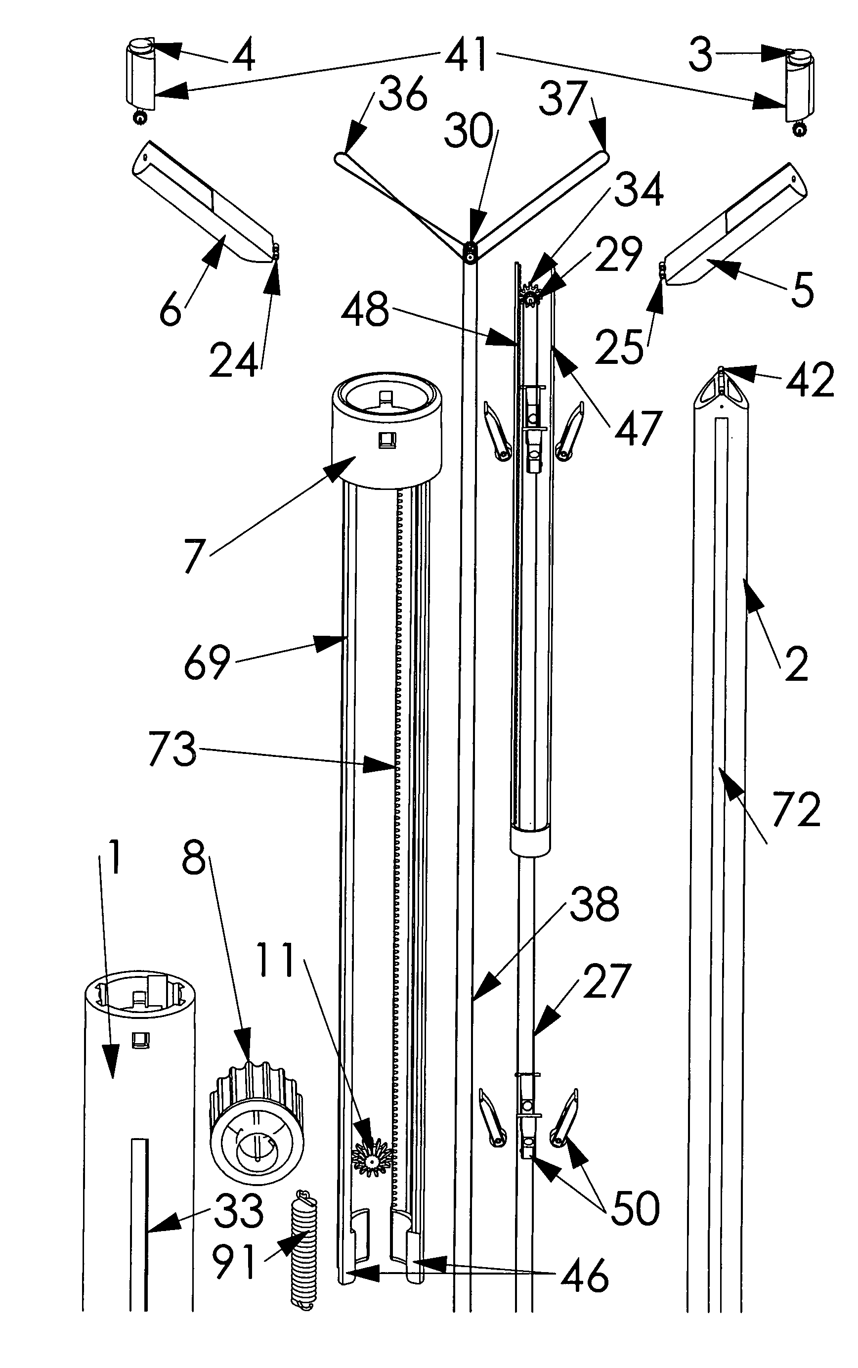
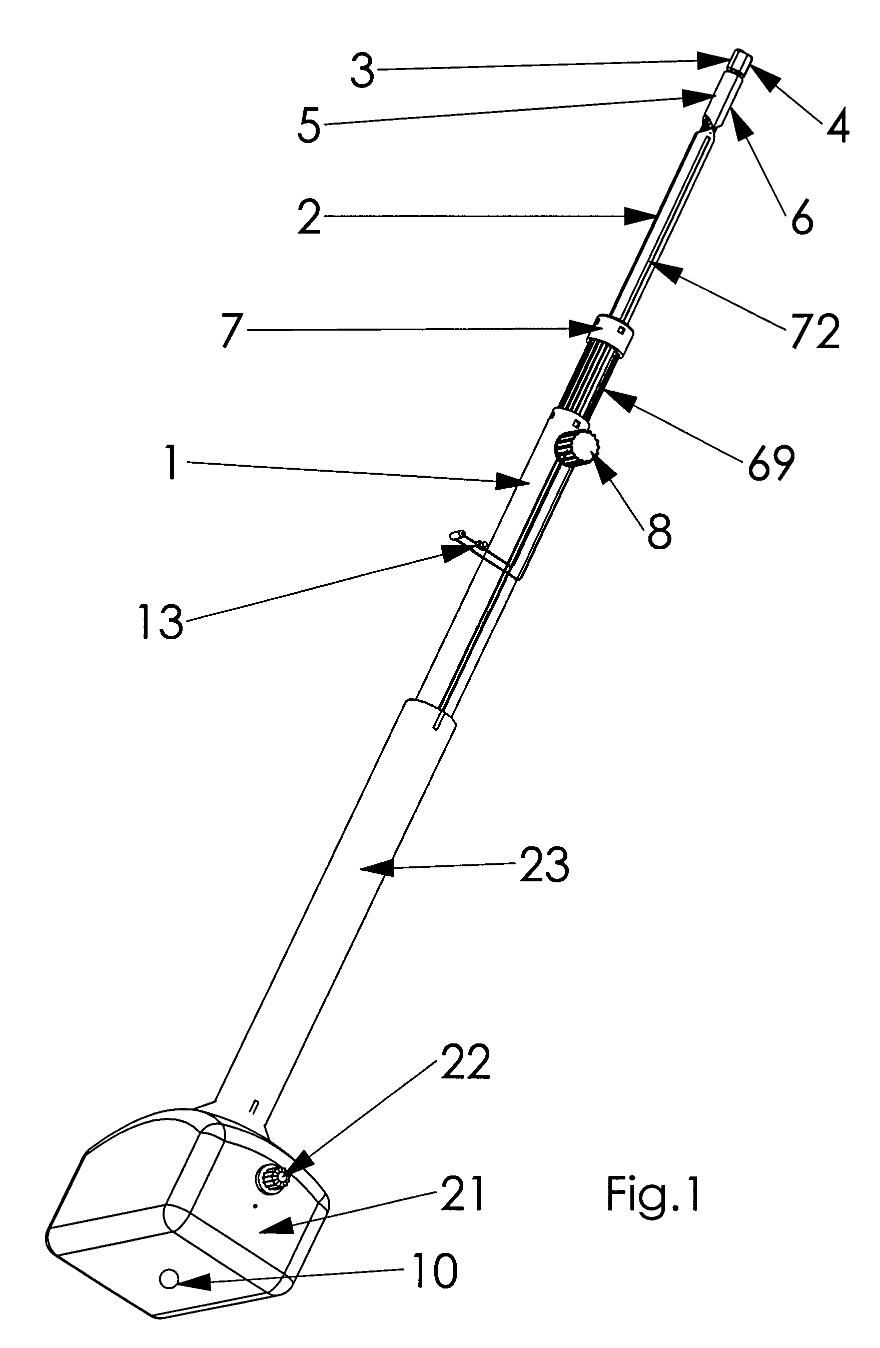
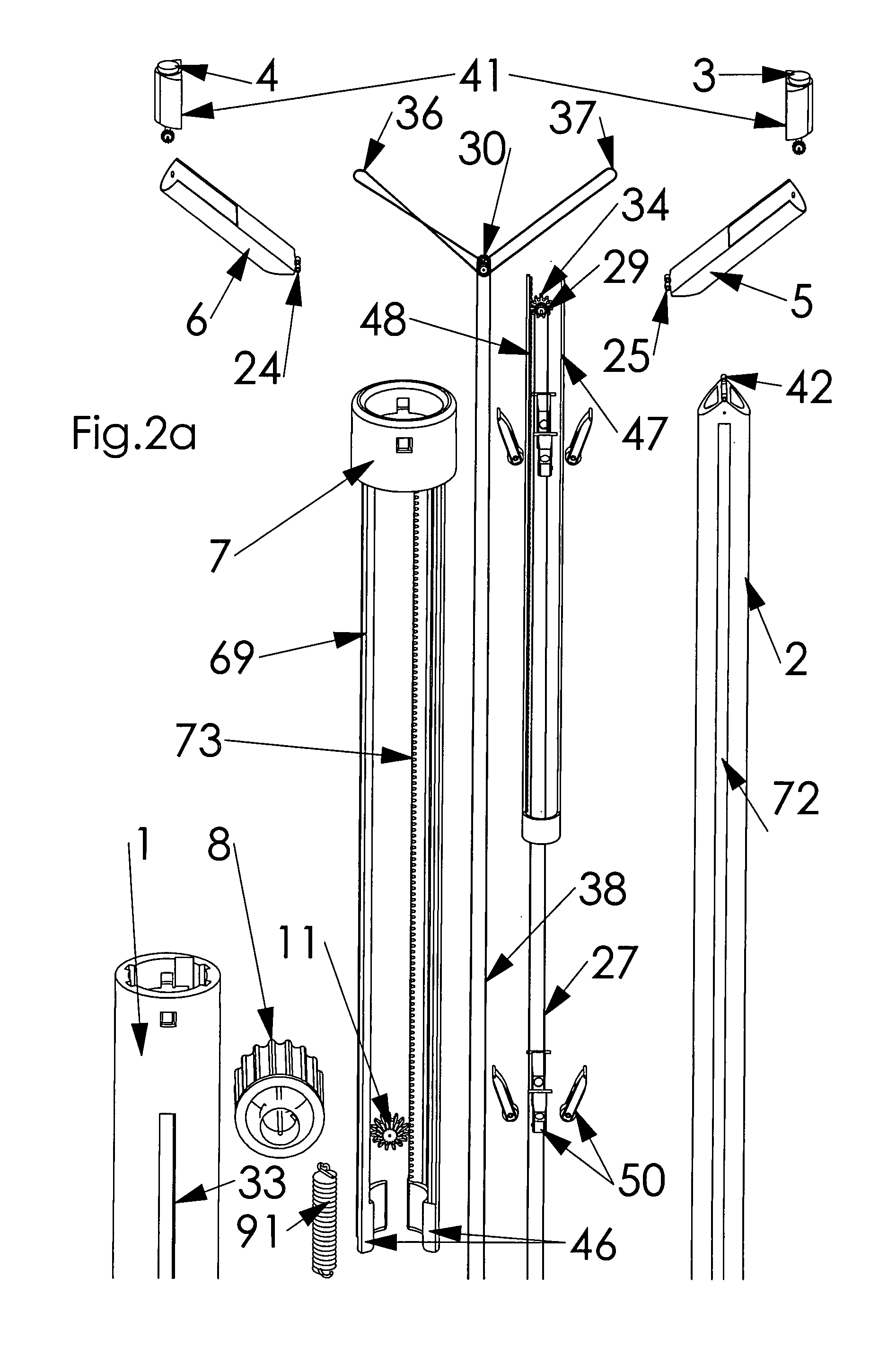
[0145]The present invention provides an endoscopic system and method that is adaptable for therapeutic applications, as well as diagnostic / sensor operation, and is capable of producing 3-dimensional human vision simulated imaging with real dynamic convergence, not virtual convergence. Applications may include use in any space, including but not limited to, intra-abdominal cavities, intra-thoracic cavities, and intra-cranial cavities. Non-medical applications are contemplated that involve viewing into areas inaccessible directly by the human eye, including but not limited to search / rescue, scientific research, and investigative applications. A main tubular shaft 2 with an elongated configuration provides the backbone of the present invention structure. Its proximal end has a shorter and wider outer shell 23 around it that is often three times the diameter of main tubular shaft 2, although not limited thereto. Outer shell 23 is used for improved operator handling of the present invent...


PUM


Abstract

An endoscopic system and method that is adaptable for therapeutic applications as well as sensor operation and is capable of producing 3-dimensional human vision simulated imaging with real dynamic convergence, not virtual convergence. Applications may include use in any space, including but not limited to, intra-abdominal cavities, intra-thoracic cavities, and intra-cranial cavities. Further, two or more diagnostic / sensor probes may be used, with at least two being the same kind to create the 3-dimensional effect, such as but not limited to, camera, ultrasound, and magnetic-resonance imaging. Diagnostic / sensor probes are each mounted to the end of a different arm, with the other ends of the two arms both being attached to the same hinge that allows them to turn freely on the same axis from side-to-side within a 180 degree angle range of movement on the distal end of a main tubular shaft system. Medical, as well as other applications, are contemplated.

Description

CROSS-REFERENCES TO RELATED APPLICATIONS[0001]NoneBACKGROUND[0002]1. Field of the Invention[0003]This invention relates to the field of medical sensing and treatment devices, specifically to an endoscopic system and method that is adaptable for therapeutic applications as well as sensor / diagnostic operation and is capable of obtaining 3-dimensional human vision simulated imaging with real dynamic convergence, not virtual convergence. Applications may include use in any space with a limited-access opening, including but not limited to, intra-abdominal cavities, intra-thoracic cavities, and intra-cranial cavities. Non-medical applications are contemplated as well, including but not limited to search / rescue, scientific research, and investigative applications. The present invention endoscopic system comprises a main tubular shaft extending between two movable probe arms and a gearbox, and the hollow interior of the main tubular shaft provides the main pathway for the belts, electrical ...

Claims


Application Information

Patent Timeline
Patent Type & Authority Patents(United States)
IPC IPC(8): A61B1/04A61B1/06H04N13/02
CPCA61B1/0008A61B1/00193A61B1/05A61B1/00097
Inventor ABOU EL KHEIR, TAREK AHMED NABIL
Owner ABOU EL KHEIR TAREK AHMED NABIL
Why Eureka
Try Eureka