
Vendor/client information system architecture

a technology of information system architecture and client, applied in the field of vendor/client information system architecture, can solve the problems of inconvenient merging of this vendor with another vendor, inconvenient manual effort, and redundant entry

Active Publication Date: 2012-01-31
THOMSON REUTERS ENTERPRISE CENT GMBH
View PDF50 Cites 18 Cited by
  • Summary
  • Abstract
  • Description
  • Claims
  • Application Information

AI Technical Summary

Problems solved by technology

Such data entry is redundant, and can create inconsistencies between the vendor information stored for the same vendor in different client databases, such as where (i) the information in one of the client's databases or instances of the service might have been entered incorrectly; (ii) one of the client's information about the vendor may have been inaccurate or out-of-date information, and such inaccurate information was therefore entered into the client's database or instance of the service; or (iii) information may have been initially entered correctly, but later becomes out-of-date (e.g. an attorney at a law firm leaves the law firm, and the law firm remembers to delete or deactivate the attorney in client #1's database but not in other client's databases).
Moreover, where the vendor data stored for the same vendor in different client databases or instances of the service is inconsistent, the merging of this vendor with another vendor may require significant manual effort to reflect the merger in each client database containing vendor information for either of the two vendors.
Such requirements may impose significant burdens on vendor users.
As one example, if clients' projects contain potential confidential data, the client-commingled data model creates potential security weaknesses.
Since all code has varying amounts bugs and errors, this model does not offer the security of other models, such as a model that maintains information about each client's project in a separate database and does not allow cross-database queries and routines.
Scalability can be another potential disadvantage of the client-commingled data model.
For example, as the number of clients, client projects, and vendors increases in a single database, the processing speed of the service may be degraded.

Method used


Image

  • Vendor/client information system architecture
  • Vendor/client information system architecture
  • Vendor/client information system architecture

Examples


Embodiment Construction

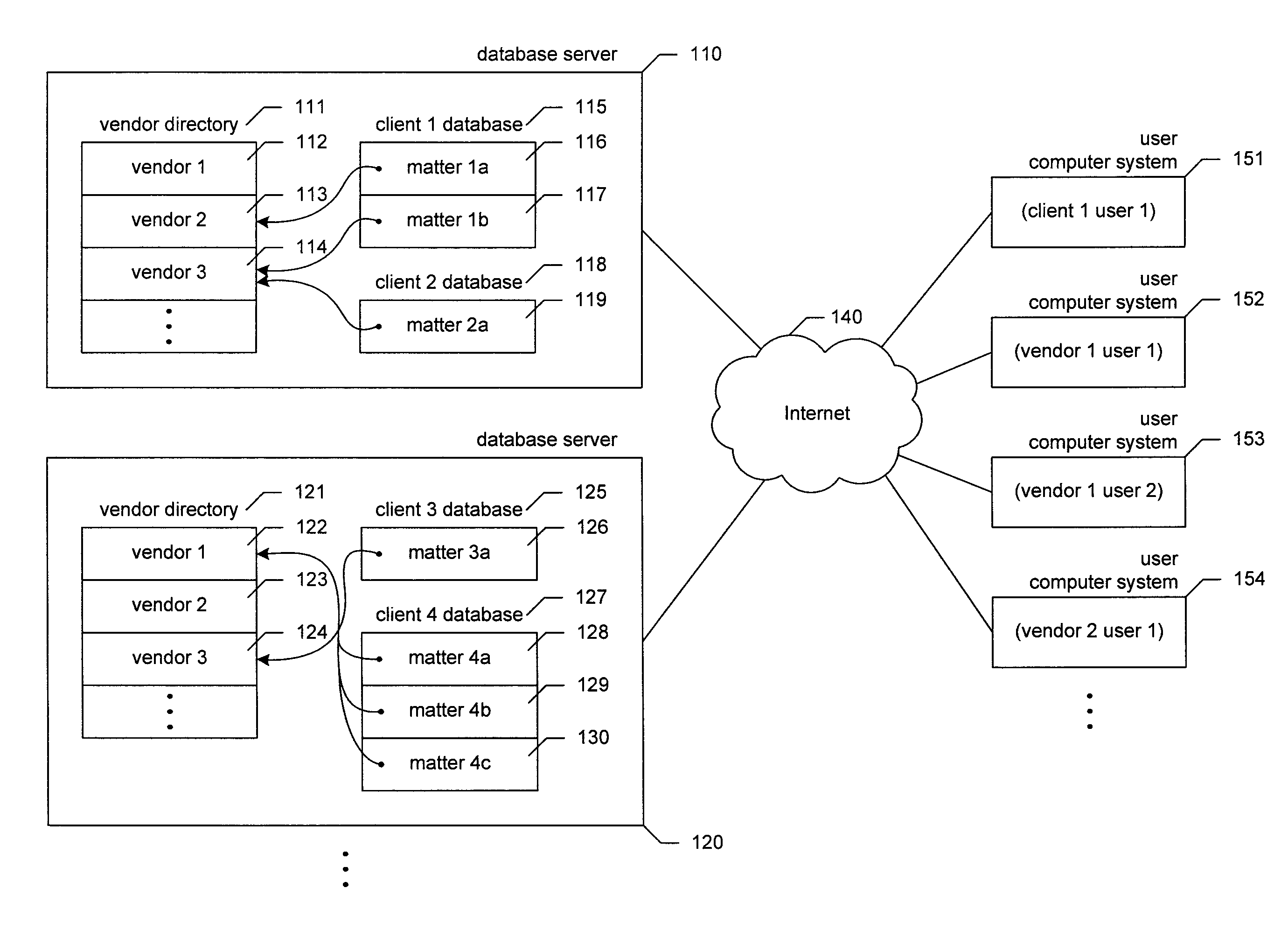
[0043]A software and / or hardware facility for storing and presenting data relating to work done for clients by vendors (“the facility”) is described. In some embodiments, the facility is incorporated as part of an ASP service used predominantly by vendors of a certain type—such as law firms—to submit bills to their clients, establish budgets and schedules, maintain status information, provide estimates and predictions of likely results, etc. In some embodiments, the facility stores certain information about vendors in a vendor directory that is separate from information about clients. For example, a vendor directory may contain, for each vendor, information about the vendor's name, locations, personnel, and users of the service. This vendor directory information is stored separately from client information, such as information identifying and describing clients and their matters, and the matters': cost estimates, schedules, predicted outcomes, billing and payment history, associated...


PUM


Abstract

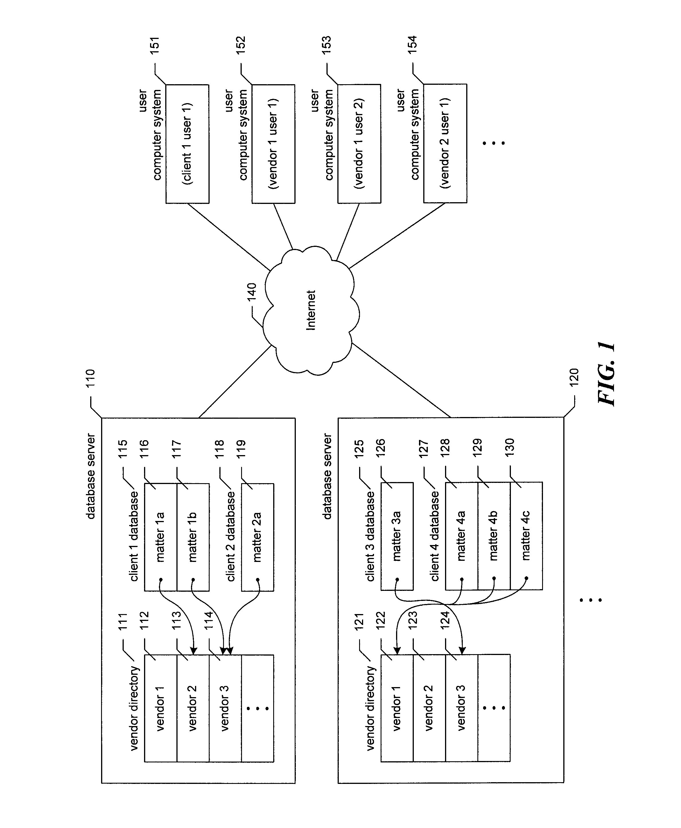
A data network storing data relating to work done by vendors for clients is described. The network includes two or more servers, each server containing (1) an exhaustive vendor data base that contains client-independent vendor data for every vendor, and (2) one or more individual client databases, each containing client information for a single client. The exhaustive vendor data base is replicated between the servers, and the client information for each client is contained by one individual client data base on one server.

Description

RELATED APPLICATIONS[0001]This application is related to one or more of the following applications, each of which is hereby incorporated by reference in its entirety: U.S. Provisional Patent Application No. 60 / 497,246 filed on Aug. 22, 2003; U.S. Provisional Patent Application No. 60 / 477,425 filed on Jun. 9, 2003; U.S. patent application Ser. No. 10 / 864,290 filed on Jun. 9, 2004; U.S. patent application Ser. No. 10 / 923,606 filed on Aug. 20, 2004; and U.S. Provisional Patent Application No. 60 / 497,247 filed on Aug. 22, 2003.TECHNICAL FIELD[0002]The described technology is directed to the field of the provision of services by vertical market application service providers.BACKGROUND[0003]It may be desirable for a client of a vendor, such as a law firm, to track work done for the client by the vendor. In particular, it may be useful for a number of clients to use a common service to track work done by a number of different vendors, in a model where each client pays to use the service to...

Claims


Application Information

Patent Timeline
IPC IPC(8): G06F7/00G06F17/30
CPCG06Q10/10G06Q10/101G06Q10/103G06F16/00
Inventor WENCEL, RONALDBOONE, RICHARDMELLING, THOMAS G.
Owner THOMSON REUTERS ENTERPRISE CENT GMBH
Learn More