Putter face and golf putter having the same

a golf putter and face technology, applied in the field of golf putter face and golf putter, can solve the problems of large initial rate loss and energy loss of the ball, adverse effects of the metal putter face on the controllability of the ball, etc., and achieve the effect of efficient topspin on the golf ball

Active Publication Date: 2012-02-07
M SYSTEM CO LTD
View PDF40 Cites 61 Cited by
  • Summary
  • Abstract
  • Description
  • Claims
  • Application Information

AI Technical Summary

Benefits of technology

[0027]As described above, the putter face of the present invention includes a plurality of microscopic protrusions which have stiffness higher than that of a golf ball and which are smaller than intervals between dimples of the golf ball, each of the plurality of microscopic protrusions having an end having a protrusion front edge surface formed in a planar shape, a periphery of the protrusion front edge surface including a plurality of linear portions facing each other and a plurality of curve portions facing each other, the plurality of linear portions extending in a horizontal direction of a face plane of the putter face which horizontal direction the face plane is supposed to have at a time of striking the golf ball, the periphery of the protrusion front edge surface forming a racetrack shape (i) which is defined by a pair of the linear portions facing each other and a pair of the curve portions facing each other and (ii) which has a longer diameter of not less than 0.3 mm but not more than 0.5 mm and (ii) a shorter diameter of not less than 0.1 mm but not more than 0.2 mm.
[0028]With the above arrangement, it is possible to efficiently create topspin on the golf ball.
[0029]Additional objects, features, and strengths of the present invention will be made clear by the description below. Further, the advantages of the present invention will be evident from the following explanation in reference to the drawings.

Problems solved by technology

However, the metallic putter faces adversely have difficulty in improving ball controllability due to their high stiffness, as compared with the non-metallic putter faces.
However, the non-metallic putter faces have such a disadvantage that the initial rate loss and energy loss of a ball is large because their coefficient of restitution is small due to their low stiffness as compared with the metallic putter faces.

Method used


Image

  • Putter face and golf putter having the same
  • Putter face and golf putter having the same
  • Putter face and golf putter having the same

Examples


Embodiment Construction

[0039]One embodiment of the present invention is described below with reference to FIG. 1 to FIG. 9.

[0040][1. Arrangement of Putter Face]

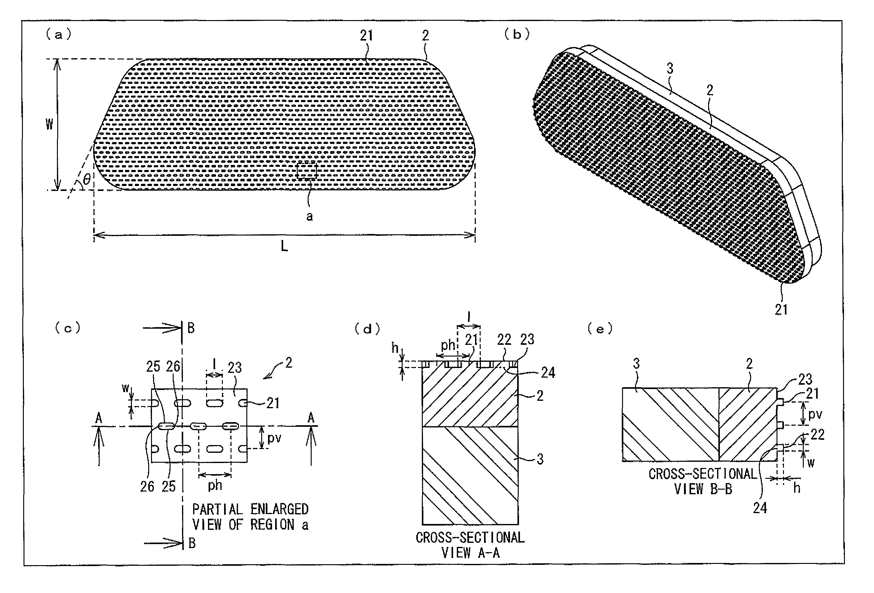
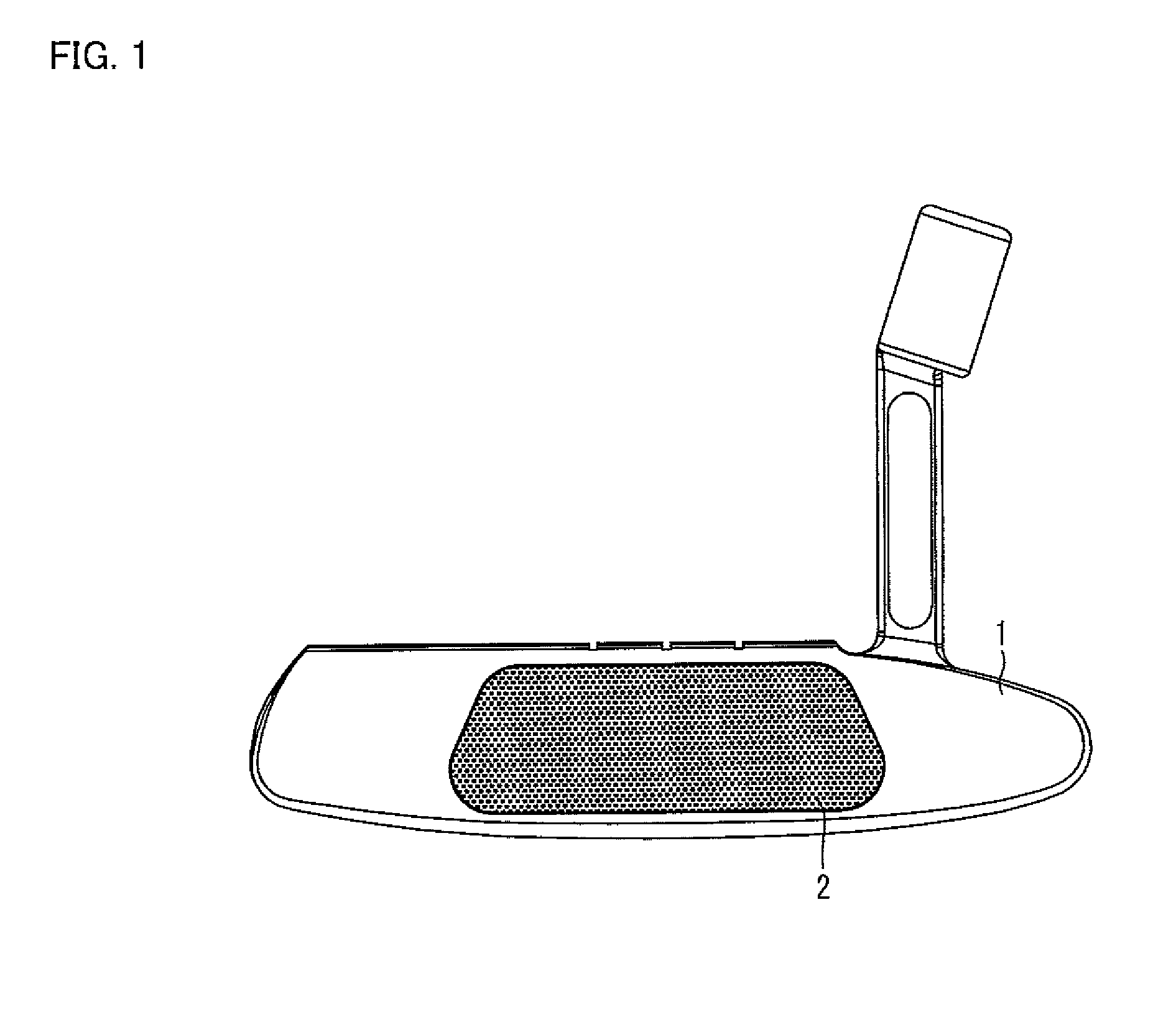
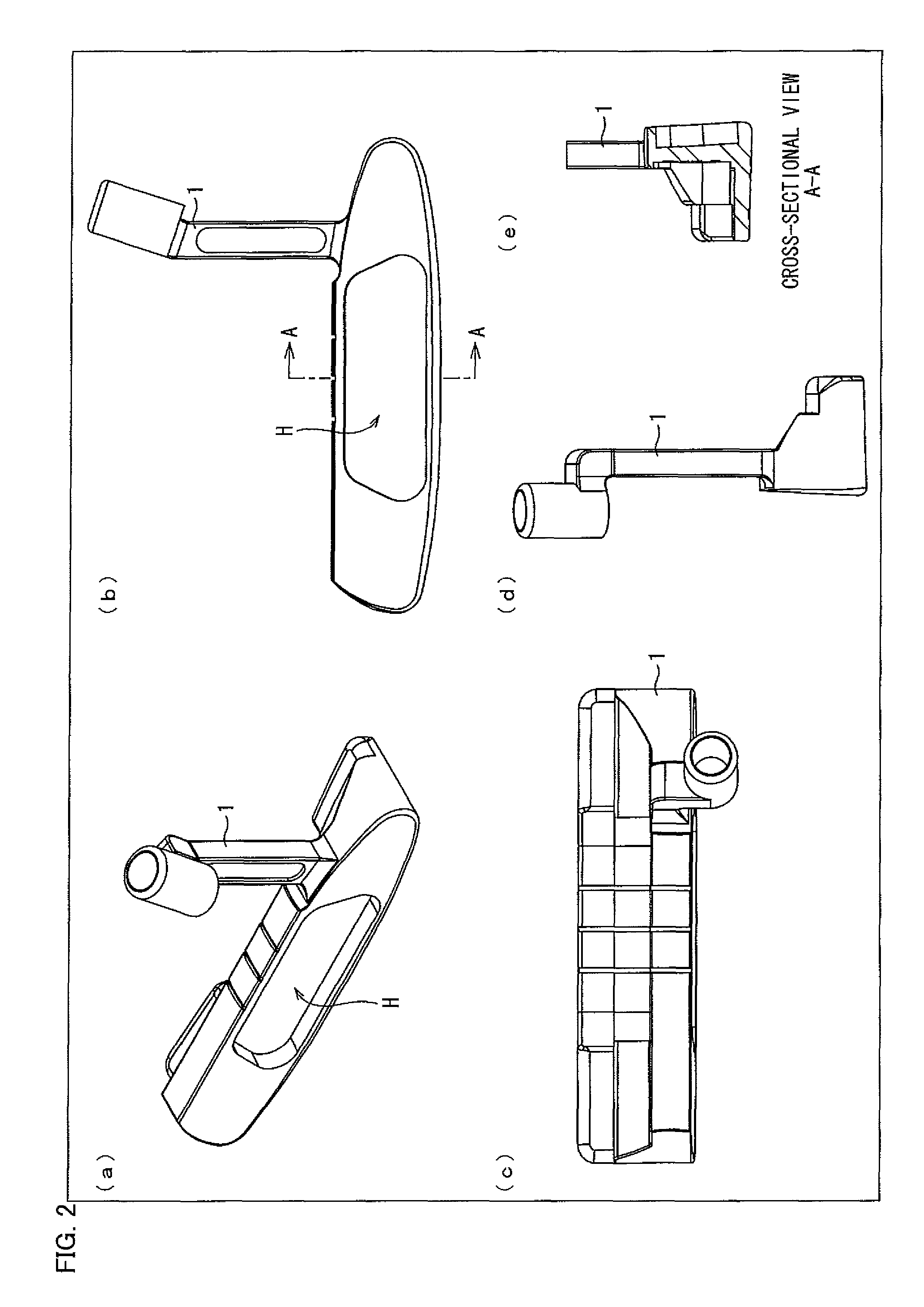
[0041]With reference to FIG. 1 to FIG. 4, initially explained is an exemplary arrangement of a head part, which is a main part of a golf putter of the present embodiment. The following deals with the head part. The other part of the golf putter of the present embodiment may be arranged in the similar manner to general golf putters, and therefore will not be explained here particularly. Further, a structure and a material of each constituent of the golf putter except for a putter face 2 explained below is not especially limited.

[0042]FIG. 1 is a view schematically illustrating an arrangement of the head part, which is a main part of the golf putter of the present embodiment.

[0043]As illustrated in FIG. 1, the head part, which is a main part of the golf putter of the present embodiment, includes a putter head 1 and a putter face 2. More specifically,...


PUM


Abstract

A putter face includes microscopic protrusions which have stiffness higher than that of a golf ball and which are smaller than intervals between dimples of the golf ball, each of the microscopic protrusions having an end having a protrusion front edge surface formed in a planar shape, a periphery of the protrusion front edge surface including linear portions facing each other and curve portions facing each other, the linear portions extending in a horizontal direction of a face plane of the putter face or striking the golf ball, the periphery of the protrusion front edge surface forming a racetrack shape (i) which is defined by a pair of the linear portions facing each other and a pair of the curve portions facing each other and (ii) which has a shorter diameter of not less than 0.1 mm but not more than 0.2 mm.

Description

[0001]This Nonprovisional application claims priority under 35 U.S.C. §119(a) on Patent Application No. 2009-285526 filed in Japan on Dec. 16, 2009, the entire contents of which are hereby incorporated by reference.TECHNICAL FIELD[0002]The present invention relates to a putter face and a golf putter including the putter face.BACKGROUND ART[0003]Conventionally, there have been two types of putter faces to be used for a head of a golf putter: a metallic putter face; and a non-metallic putter face, which is made from a synthetic resin or the like.[0004]Metallic putter faces have such an advantage that due to their large coefficient of restitution associated with their high stiffness, initial rate loss and energy loss of a ball is small as compared with non-metallic putter faces. However, the metallic putter faces adversely have difficulty in improving ball controllability due to their high stiffness, as compared with the non-metallic putter faces.[0005]On the other hand, the non-metall...

Claims


Application Information

Patent Timeline
Patent Type & Authority Patents(United States)
IPC IPC(8): A63B53/04A63B102/32
CPCA63B53/0487A63B2053/0416A63B2053/0441A63B2053/0408A63B2209/00A63B53/0441A63B53/0408A63B53/0416
Inventor MIYAMICHI, SABURO
Owner M SYSTEM CO LTD
Why Eureka
Try Eureka