Wireless diagnostic system

a diagnostic system and wireless technology, applied in the field of test equipment interconnection, can solve the problems of affecting the accuracy of test data, and engendering delays that are generally undesirable, so as to reduce the cost and facilitate the use

Active Publication Date: 2012-02-07
COMSONICS
View PDF17 Cites 17 Cited by
  • Summary
  • Abstract
  • Description
  • Claims
  • Application Information

AI Technical Summary

Benefits of technology

[0006]It is therefore an object of the present invention to provide a test instrument system which is compact, light weight, rugged, convenient to use and of reduced cost due to elimination of redundant components while being capable of potentially simultaneous communications with an operator (e.g. through a companion PC, PDA or the like and concurrent documentation of test results in a manner which is virtually free from human error or possible falsification.
[0008]It is a further object of the invention to provide a substantially real-time communication system which will support analysis for detecting trends, evaluating personnel performance and / or making management decisions including workforce management and scheduling with increased efficiency and workforce effectiveness; which additional analysis facility can be included in the overall system in accordance with the invention for end-to-end monitoring and management and efficiency improvement of a Broadband Communication System.

Problems solved by technology

In general, due to the complexity of test protocols and combinations of test sequences of each such protocol, test instruments currently in use or available are generally programmed to carry out relatively long sequences of test protocols autonomously upon initiation of testing by an operator.
However, performing the downloading after return of the test instrument to a central facility or the like engenders delays that are generally undesirable to installation and / or maintenance personnel since they are generally compensated based upon the number of repair or installation calls performed (but not necessarily whether the installation and / or maintenance was performed completely, correctly or effectively).
From the standpoint of the cable system administrator or operator (as distinct from the test instrument operator, installation and / or maintenance personnel), while the downloading of test data from the test instrument is desirable for archival storage and performance documentation purposes, delays incurred by downloading test data at the central facility or the like is also undesirable since it cannot be performed while the installation and / or maintenance personnel remain on site and thus has no potential for reducing frequency of “call-backs” to complete, correct or revise installation or maintenance work.
Doing so manually by technical maintenance and installation personnel is becoming increasingly frequent to close work orders in a more timely fashion even though it is cumbersome, subject to errors or possible falsification (unless automated data downloading from the test instrument to the portable data processor is provided in the field; requiring each data processor to be separately and specially programmed for the purpose) and requires much redundant structure to be provided by the test instrument and the data processor; each of which must necessarily be capable of operating as a stand-alone device.
However, the personal computer or communication device cannot perform testing and currently available testing instruments cannot perform communications of the test data gathered other than possibly by storing the data for later downloading.
In this regard, it should be understood that, as Broadband Communications Systems corresponding to a single provider become increasingly large or multiplied, management of the technical field staff becomes an ever-increasingly important and complex issue.
Further, downloading test sequence instructions reduces the likelihood of corruption of such signals and increases the likelihood that any corruption of such signals will be discovered.
Moreover, a given system may exhibit certain types of problems much more often than others and which are revealed by test sequences which should be normally performed whenever any type or one of certain types of work is performed on the distributed system while some diagnostic testing sequences may be performed only rarely.

Method used


Image

  • Wireless diagnostic system
  • Wireless diagnostic system
  • Wireless diagnostic system

Examples


Embodiment Construction

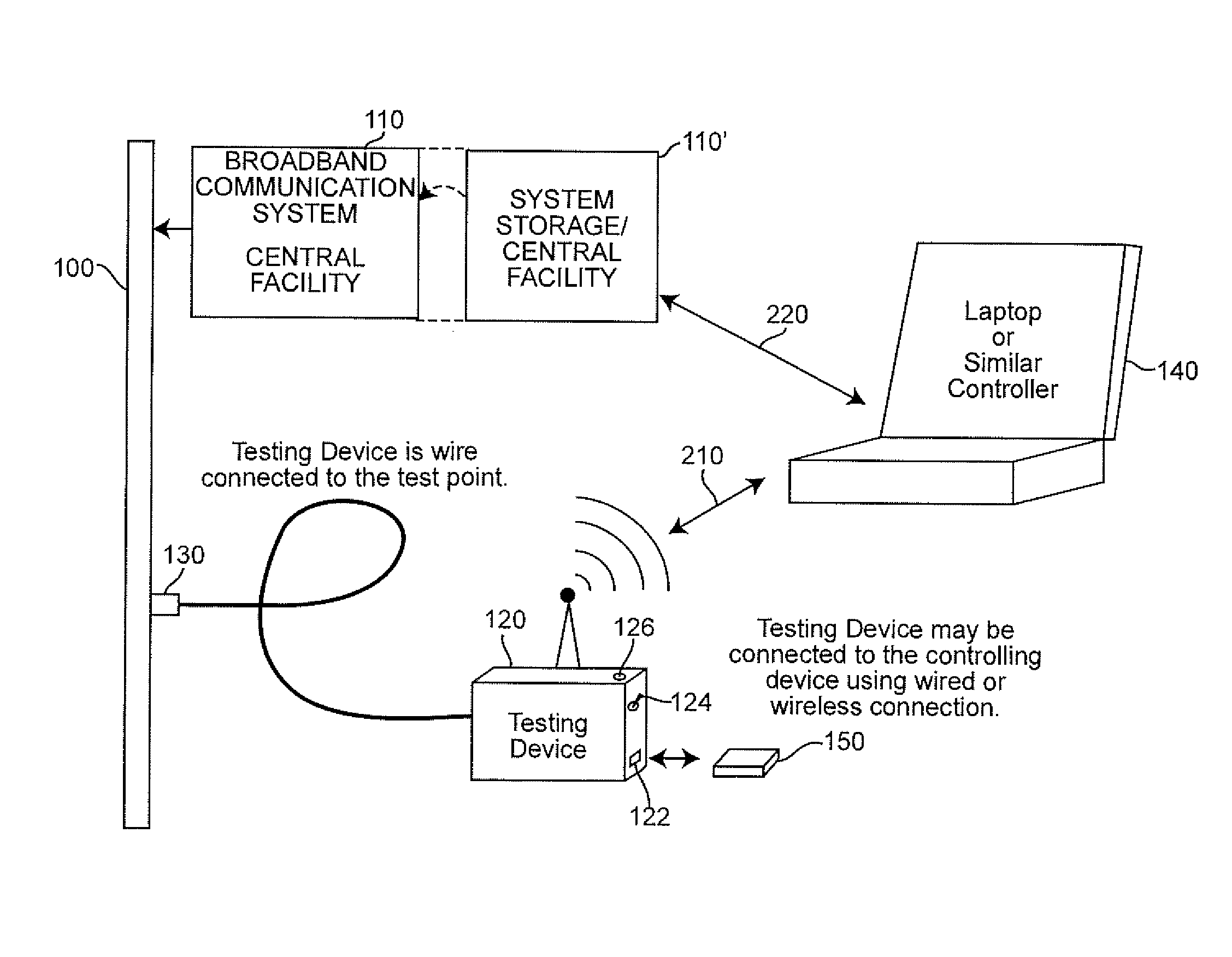
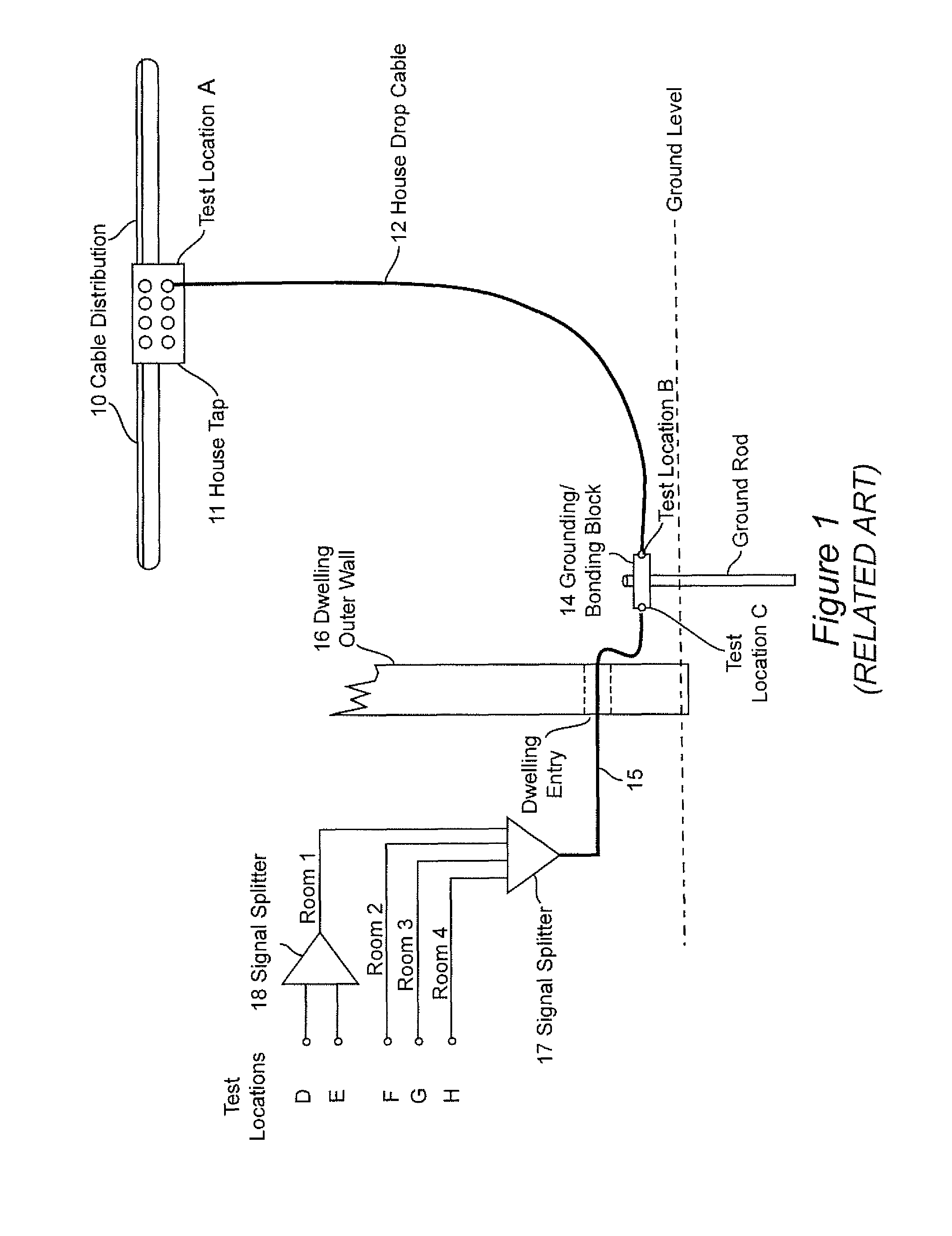
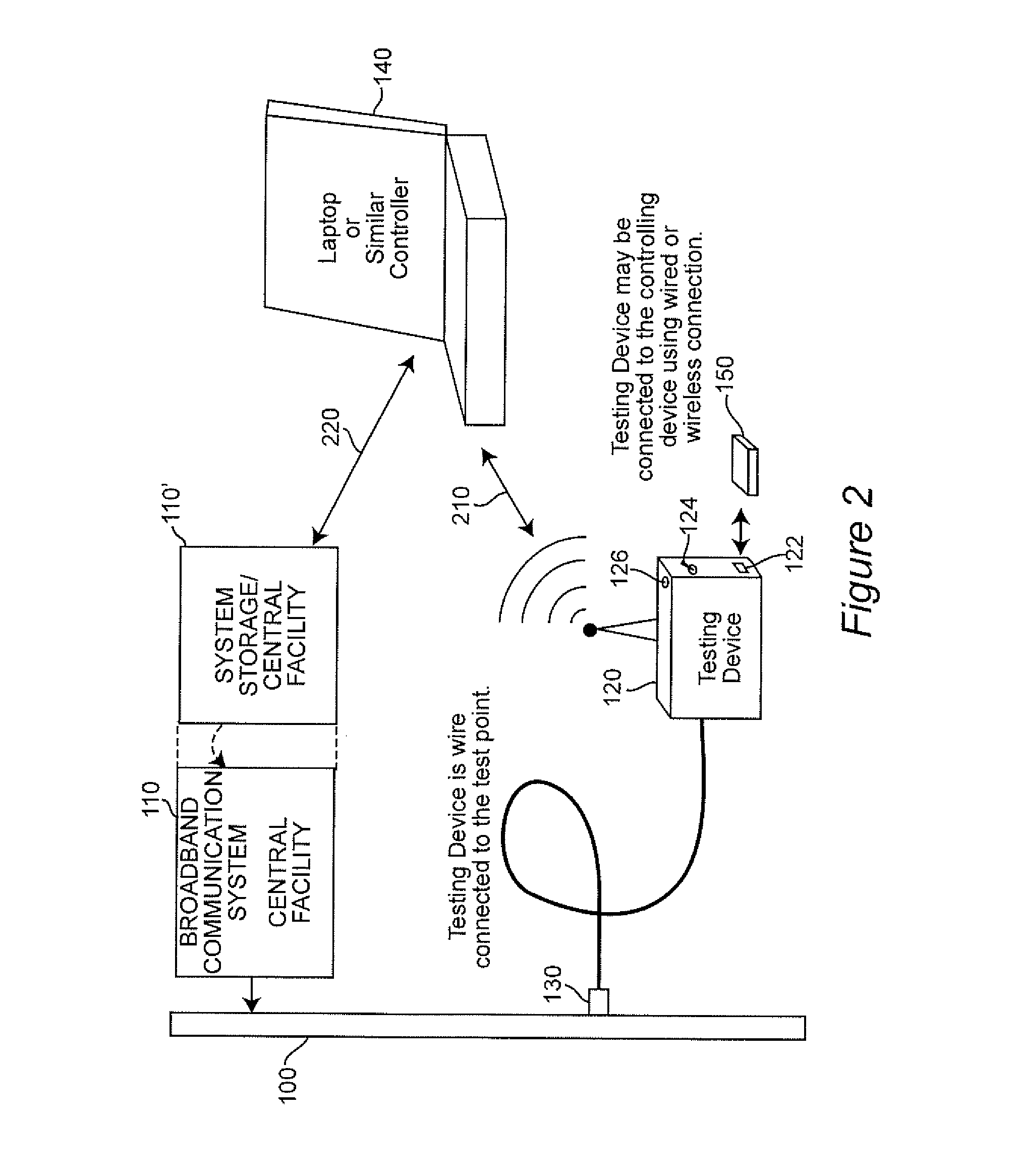
[0016]Referring now to the drawings, and more particularly to FIG. 1, there is schematically shown an exemplary cable drop installation to which the invention is applicable. Since FIG. 1 is arranged, to facilitate an understanding of the application of the invention, no portion thereof is admitted to be prior art in regard to the present invention. Further, at the level of abstraction illustrated, the invention may or may not be included in the illustration of FIG. 1 and FIG. 1 has thus been designated “Related Art”. It is also to be understood that while the invention will be described in connection with a Broadband Communications System (sometimes, for convenience, referred to hereinafter as a cable system) in which the invention is particularly advantageous, the invention is also applicable to other types of distributed systems such as power, water and natural gas distribution systems and other utilities as well as dedicated communication or data processing systems or networks an...


PUM


Abstract

Results of field testing of portions of a distributed system such as a Broadband Communications System from a testing device to a controller which downloads programmed test protocols and sequences thereof to the separate testing device over a wired or wireless link and thereafter can be used to control the testing device as well as display test results and provide analysis of the test results and suggest procedures to technical personnel. The controller then can transmit the test data to a central facility or distribution hub in substantially real-time together with work performance data where full technical analysis can be performed. The test data and results of analysis can then be distributed as desired such as to a management analysis facility to support improvement of efficiency of the system and the operation thereof.

Description

FIELD OF THE INVENTION[0001]The present invention generally relates to test equipment interconnectivity for testing the operating condition of a geographically distributed system such as a Broadband Communications System and, more particularly, for providing transmitted results of testing to an operator of the test equipment as well as logging and / or analyzing test results at another portion of the system and / or independently of the system such as a central facility or a combination thereof.BACKGROUND OF THE INVENTION[0002]In recent years, many systems have been developed for various purposes, wherein the systems are distributed over a potentially large area. The distribution of portions of the systems thus requires that testing of the operational conditions of the system be performed locally to respective portions of the system and requires test equipment and trained operators thereof who are also trained to effect most, if not all, types of installation, repair or maintenance to p...

Claims


Application Information

Patent Timeline
Patent Type & Authority Patents(United States)
IPC IPC(8): G06F11/00
CPCG06F11/2294H04L43/12H04M1/24H04L43/50H04W24/04H04M3/30H04M3/301
Inventor ZIMMERMAN, DENNIS A.
Owner COMSONICS
Why Eureka
Try Eureka