Metering device

a metering device and metering technology, applied in the direction of volume metering, laboratory glassware, instruments, etc., can solve the problem of limiting a guiding groove, achieve the effect of avoiding damage to the sensing device and facilitating the automatic separation of pipette and syring

Active Publication Date: 2012-02-14
EPPENDORF SE
View PDF8 Cites 13 Cited by
  • Summary
  • Abstract
  • Description
  • Claims
  • Application Information

AI Technical Summary

Benefits of technology

[0012]In the metering device of the present invention, by rotation around the symmetry axis of the cylinder-plunger system of the syringe which is inserted into the metering device, i.e. around the axis of the metering device, a syringe when being inserted is aligned by the co-operation of the alignment nose with the axial guiding means into an angular position in which each sensing surface of the syringe provided for this is axially directed towards a sensing means. In this, with its fastening portion formed on the cylinder and preferably being annular-shaped and located preferably at the upper end of the cylinder, and also with its plunger rod, the syringe arrives in the fastening position in which it is detachably held by way of the fastening device. The pipette can sense the sensing surfaces with its sensing device and acquire the information about the syringe and / or its condition that is contained in the number and / or the arrangement and / or the axial position of the sensing surfaces. This information may be processed and / or displayed via mechanical and / or electric and / or optical analysing units and / or via display units. Applying a great force it is possible to turn a syringe made of polypropylene or another soft elastic plastic material away from this fastening position without releasing the fastening means before, wherein each alignment nose is pressed along an associated guiding means under deformation. However, the present invention prevents that a damage of the preferably annular sensing device is accompanied by this. This is achieved by the preferably annular guiding means, which receives the at least one alignment nose in at least one indentation, provided that the syringe is correctly directed towards a sensing means with every sensing surface that is provided for this. When twisting the syringe, the at least one sensing surface slides from out the at least one indentation to the at least one raised surface which has a greater distance from the sensing device, so that the syringe cylinder is displaced away from the sensing device. In this, the sensing surfaces are displaced away from the annular sensing device, so that they do not damage the sensing means projecting from there and the sensing means are actuated no more. In the twisting, the fastening portion is preferably moved away from the annular sensing device so far that the sensing surfaces just no more touch the sensing means. Thus, the present invention takes the finding into account that a forced twisting of the syringe out of its fastening position in the metering device cannot be prevented due to the soft elastic plastic materials that are used for the syringe. However, the metering device of the present invention prevents damage of the expensive sensing device by having means which transform a rotation of the syringe with respect to the pipette into a shifting apart of fastening portion and sensing device.
[0018]In principle, the preferably annular sensing device may be disposed rigidly with respect to the accommodation. In a preferred embodiment, it is supported in the accommodation by way of at least one spring means acting axially against the displacement direction of the fastening portion. The spring means catches when the pipette is inserted. Through this, tolerances are compensated and damage of the sensing device is avoided.
[0019]Springy holding means can exist for the fastening portion, so that fastening portion and sensing device can be displaced away from each other when the syringe is rotated. For instance, the fastening devices can be realised in a springy fashion. Further, it is possible to make the fastening portion springy on locations that are held by the fastening devices. According to a preferred embodiment, the preferably annular guiding means is connected to the sensing device and is supported in the accommodation by way of the at least one spring means. In this embodiment, twisting of the syringe that is detachably held in the pipette results in a movement of the annular guiding means, accompanied by taking along the preferably annular sensing device, wherein the at least one spring means catches in. As a result, the sensing device evades from the sensing surfaces of the syringe and will not be damaged.
[0020]The springy realisation of sensing devices, and as the case may be of guiding means, facilitates the automatic separation of pipette and syringe after releasing the fastening means.
[0023]Gradual removal of the fastening portion from the sensing device when the syringe is rotated in the pipette can be made sure by a suitable contour of the alignment nose in particular. For this purpose, the alignment nose may be rounded or chamfered on both side at the upside. According to a preferred embodiment, the guiding contour gradually ascends between the indentations and the raised parts. This favours a smooth gliding of the alignment noses over the guiding contour in the rotation of the syringe, in particular in co-operation with rounded or chamfered sides of the at least one alignment nose. According to a further embodiment, the transitions between the indentations and the raised parts are ramp-shaped and / or rounded.

Problems solved by technology

Also, parallel axial guiding bridges can limit a guiding groove.

Method used


Image

  • Metering device
  • Metering device
  • Metering device

Examples


Embodiment Construction

[0047]While this invention may be embodied in many different forms, there are described in detail herein a specific preferred embodiment of the invention. This description is an exemplification of the principles of the invention and is not intended to limit the invention to the particular embodiment illustrated

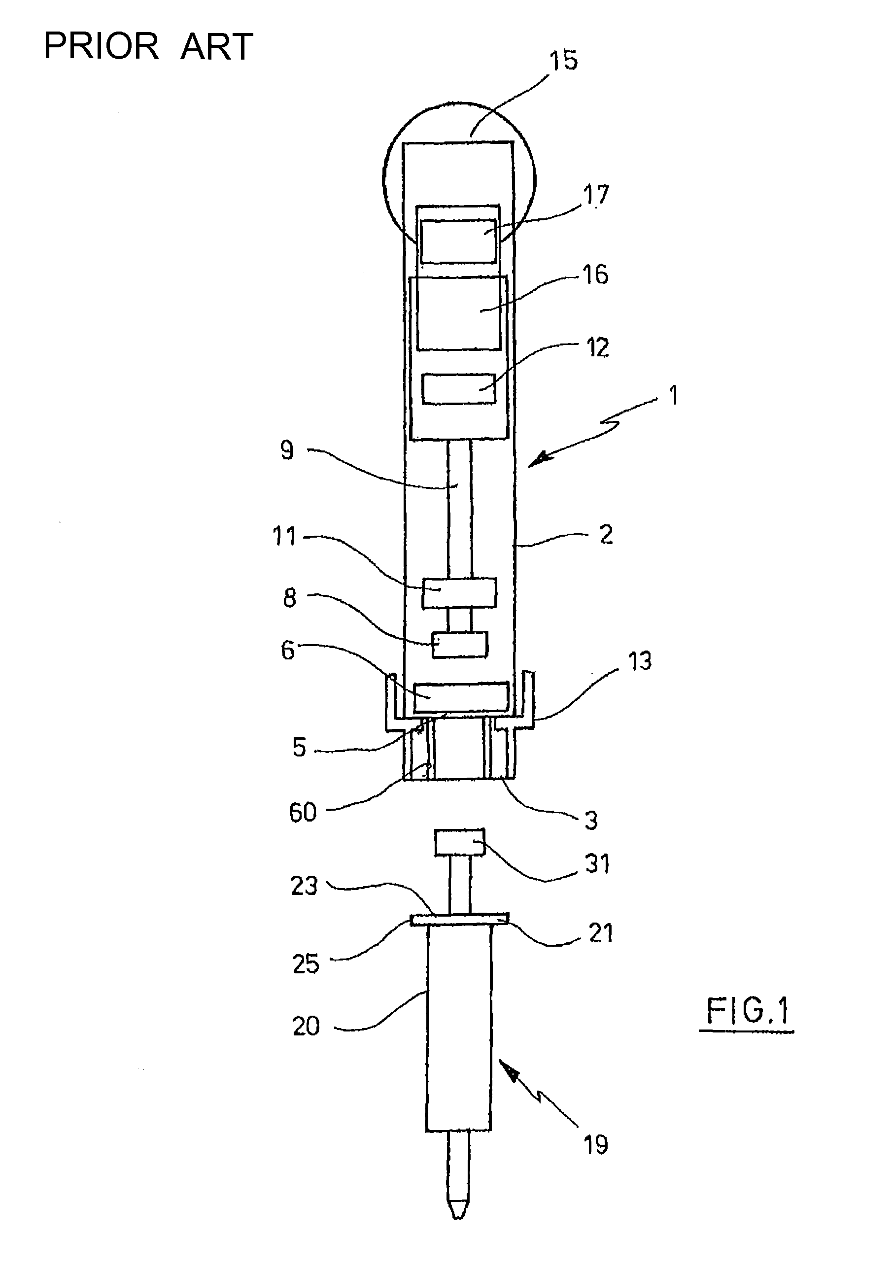
[0048]In the present application, the indications “up” and “down”, as well as “upside” and “downside” refer to the preferred alignment of the metering device in the operation, wherein the metering device is aligned vertically and a syringe connected to the metering device is disposed below the metering device.

[0049]According to FIG. 1, a metering device 1 of the state of the art actuated by hand comprises a casing 2, which has an accommodation 3 at the downside, which is accessible from the outside through an axial opening 4 on the lower end.

[0050]The accommodation 3 has an approximately circular cross section.

[0051]An annular sensing device 6 is disposed on the bottom 5 of th...


PUM


Abstract

A metering device for utilization with a syringe, which features on a syringe cylinder a fastening portion with at least one axially directed sensing surface projecting from the upside, and at least one alignment nose projecting from the outer perimeter of the fastening portion, and a plunger with a plunger rod, the metering device having an accommodation for the fastening portion of the syringe cylinder, the accommodation having an axial opening for axially inserting the fastening portion into a fastening position, a sensing device disposed in the accommodation with at least one sensing means projecting from a basis surface of the sensing device facing the axial opening, for sensing the at least one sensing surface of a fastening portion inserted in a fastening position.

Description

CROSS-REFERENCE TO RELATED APPLICATIONS[0001]This application claims priority to provisional U.S. patent Application No. 61 / 171,208, entitled Metering Device filed Apr. 21, 2009, the entire contents of which is incorporated herein by reference in its entirety.STATEMENT REGARDING FEDERALLY SPONSORED RESEARCH[0002]Not applicable.BACKGROUND OF THE INVENTION[0003]The present invention is related to a metering device for utilisation with a syringe.[0004]Metering devices serve for metering liquids and are used in biological, chemical and medical laboratories in particular. In the realisation as dispensers, they permit the stepwise delivery of a liquid from a syringe. The metering amount per delivery step can be adjustable in this. A dispenser with metering amount adjustment is known from DE 29 26 691 C2, the entire contents of which is incorporated herein by reference.[0005]Furthermore, pipettes are known as metering devices, by which an amount of liquid defined or adjustable via the appa...

Claims


Application Information

Patent Timeline
Patent Type & Authority Patents(United States)
IPC IPC(8): B01L3/02
CPCB01L3/0217B01L3/0279G01F11/029B01L3/0227B01L3/0275B01L2200/023B01L2200/025G01N35/1016G01N2035/1062
Inventor REICHMUTH, BURKHARDT
Owner EPPENDORF SE
Why Eureka
Try Eureka