
Circuit breaker

a circuit breaker and circuit technology, applied in the field of circuit breakers, can solve problems such as generating restrictions

Inactive Publication Date: 2012-02-14
MITSUBISHI ELECTRIC CORP
View PDF12 Cites 19 Cited by
  • Summary
  • Abstract
  • Description
  • Claims
  • Application Information

AI Technical Summary

Benefits of technology

[0007]The present invention is made to solve the aforementioned problem, and an object of the present invention is to obtain a circuit breaker in which restriction of an arrangement relationship on the connection conductor side with respect to the movable rod side of the circuit breaker is reduced and miniaturization is achieved.
[0009]According to the circuit breaker of the present invention, the connection portion on one end side of the flexible conductor is connected to the terminal by keeping the width direction parallel to the drawing direction of the movable side connection conductor and by keeping the longitudinal direction parallel to the connecting / disconnecting direction; and in the state where the intermediate portion is twisted and bent in the right angle direction toward the movable side connection conductor to invert the front and back, the other end side of the connection portion is connected to the movable side connection conductor by keeping the width direction parallel to the connecting / disconnecting direction. Therefore, restriction in arrangement of the movable side connection conductor is reduced; and, in the case where the flexible conductor is used by locating in parallel, distance in the interphase direction can be reduced and the circuit breaker can be miniaturized.
[0011]Furthermore, in the mounting of the flexible conductor similar to the above mention, the other end side of the connection portion is connected to the movable side connection conductor by keeping the laminating direction parallel to the connecting / disconnecting direction; and therefore, a circuit breaker with a high degree of flexibility in mounting directions of the flexible conductor and the movable side connection conductor can be obtained.

Problems solved by technology

In order to satisfy necessary flexibility and durability as the flexible conductor, a certain length is required for a flexible portion all anyhow and it is difficult to directly bend the belt-like conductor in a direction orthogonal to the longitudinal direction; and therefore, there is a problem in that restriction is generated in arrangement of the coupling of the movable rod and the movable side connection conductor.

Method used


Image

  • Circuit breaker
  • Circuit breaker
  • Circuit breaker

Examples


embodiment 1

Preferred Embodiment 1

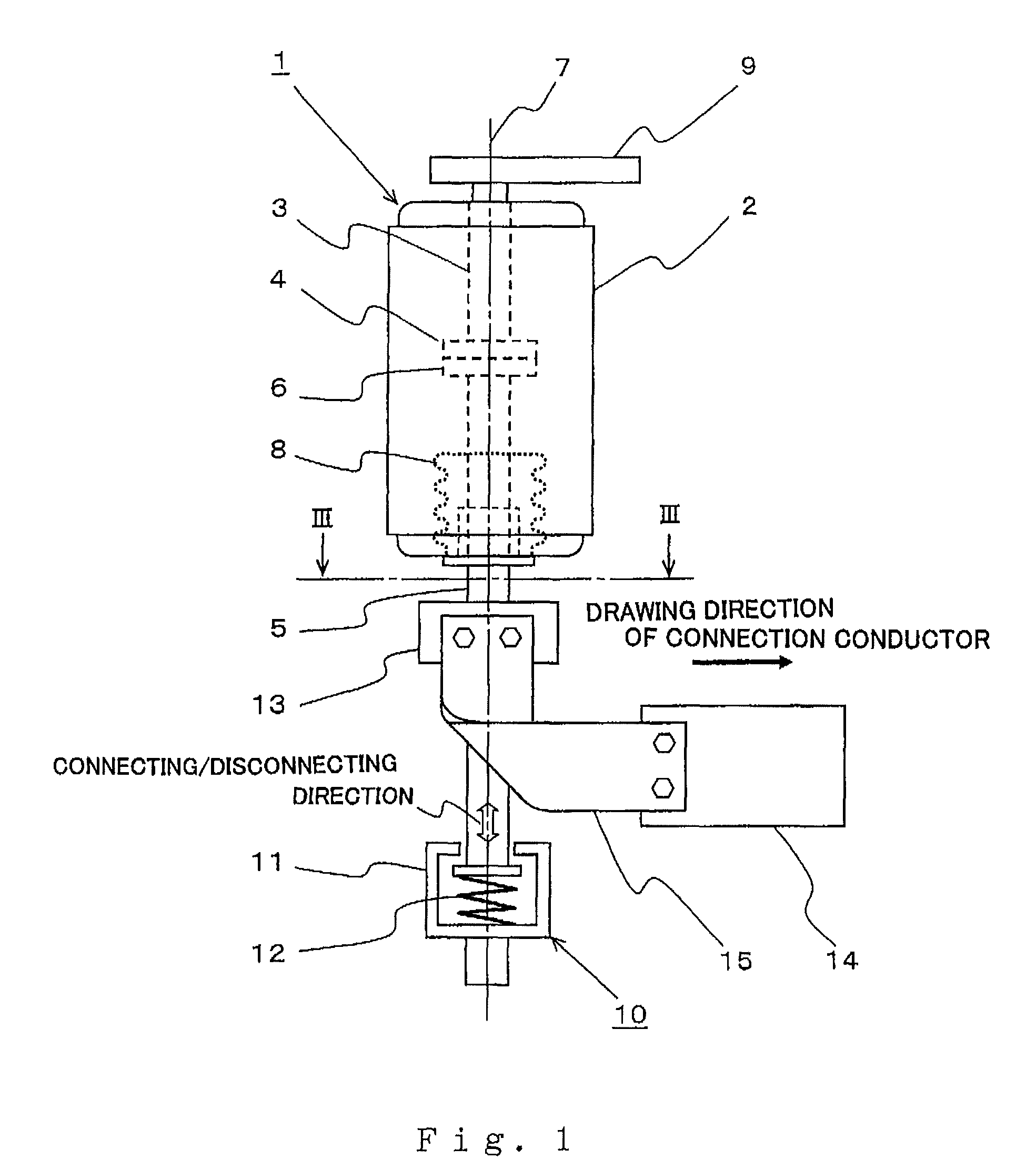
[0019]Hereinafter, a circuit breaker according to a preferred embodiment 1 will be described on the basis of figures. In the present preferred embodiment, description will be made as an example in the case of a vacuum circuit breaker which uses a vacuum valve in a switching portion as a circuit breaker.

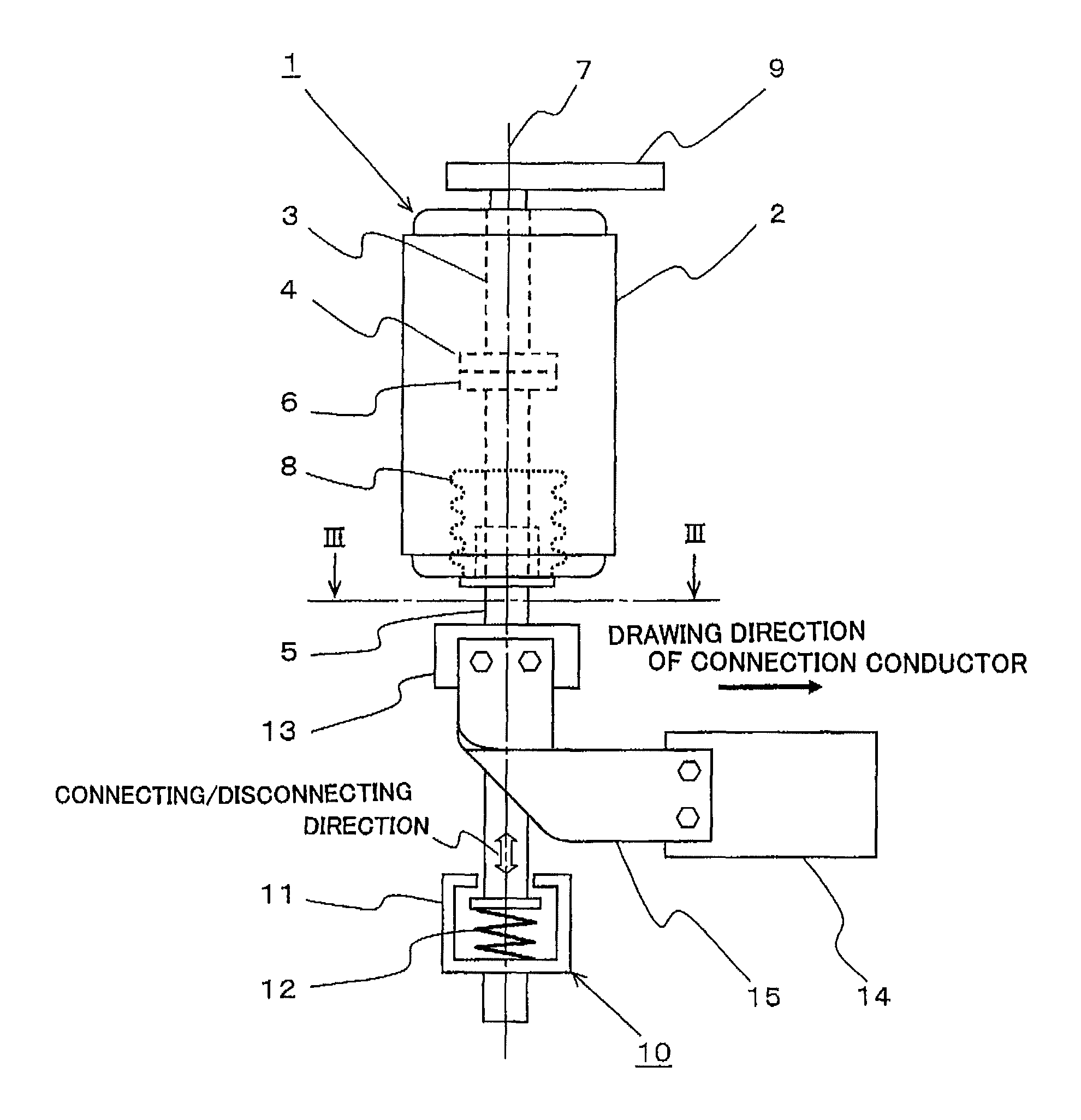
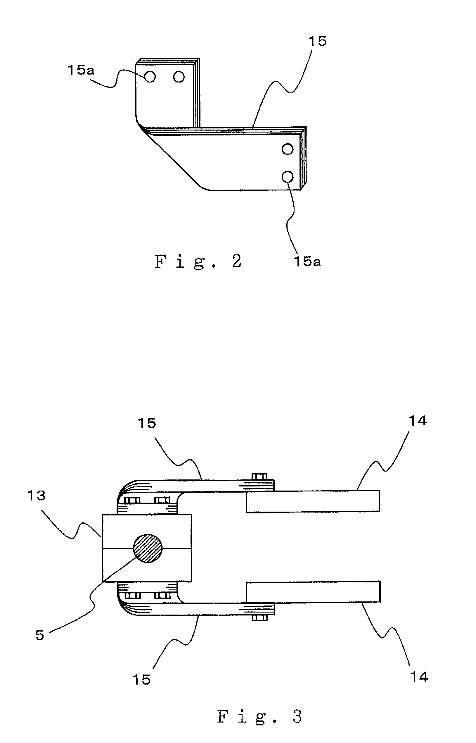
[0020]FIG. 1 is a side view of the vacuum circuit breaker according to the preferred embodiment 1, and only a major portion necessary for the description is shown. In the figure, the vacuum circuit breaker has three phase vacuum valves 1 which are arranged in three units in a direction perpendicular to the page space by being supported by an insulation supporting member (not shown in the figure); and the figure shows a state where only front one phase is seen. The vacuum valve 1 is configured such that a fixed electrode 4 coupled to a fixing rod 3 and a movable electrode 6 coupled to a movable rod 5 are arranged to be capable of being connected / disconnected on an...

embodiment 2

Preferred Embodiment 2

[0038]FIG. 4 is a side view showing a relevant portion of a circuit breaker according to a preferred embodiment 2. Constituent elements equivalent to those of FIG. 1 of the preferred embodiment 1 are shown by the same reference numerals and their description will not be repeated, but will be described covering mainly a different point. The different point is a mounting direction of a flexible conductor.

[0039]A flexible conductor 16 of the present preferred embodiment is the same as the case shown in FIG. 2 in that a plurality of sheets of a thin copper band are laminated and connection portions are provided on both ends.

[0040]One end side of the connection portion is connected to a terminal 13 by keeping a width direction parallel to a drawing direction of a movable side connection conductor 14 and by keeping a longitudinal direction parallel to a connecting / disconnecting direction; and in a state where an intermediate portion of the longitudinal direction is t...


PUM


Abstract

A flexible conductor which connects the movable rod side of a circuit breaker and a movable side connection conductor is devised to miniaturize the circuit breaker. In the circuit breaker in which a fixed electrode and a movable electrode are arranged to be capable of being connected / disconnected, and a terminal provided on the movable rod of the movable electrode and the movable side connection conductor arranged in the vicinity of the terminal are connected by a flexible conductor, the flexible conductor is formed by laminating a plurality of sheets of a belt-like metal sheet and has connection portions on both ends; one end side of the connection portion is connected to the terminal by keeping a width direction parallel to a drawing direction of the movable side connection conductor and by keeping a longitudinal direction parallel to a connecting / disconnecting direction; and in a state where an intermediate portion is twisted and bent in a right angle direction toward the movable side connection conductor to invert the front and back, the other end side of the connection portion is connected to the movable side connection conductor by keeping the width direction parallel to the connecting / disconnecting direction.

Description

BACKGROUND OF THE INVENTION[0001]1. Field of the Invention[0002]The present invention relates to, for example, a circuit breaker such as a vacuum circuit breaker using a vacuum valve and, in more detail, relates to a flexible conductor which connects the movable rod side and a connection conductor.[0003]2. Description of the Related Art[0004]A vacuum circuit breaker in which a known vacuum valve is used is shown in FIG. 6. The figure is a side view showing a state where the vacuum valve is closed. In the figure, a vacuum valve 20 is configured such that a fixed electrode 22 and a movable electrode 23 are contained inside a vacuum vessel 21 to be capable of being connected / disconnected. The fixed electrode 22 side is fixed by being connected to a fixed side connection conductor 26 which is fixed to a mounting plate 24 via an insulation supporting member 25. On the other hand, on the movable electrode 23 side, a movable rod 27 is led out; and one end side of a flexible conductor 29 is...

Claims


Application Information

Patent Timeline
Patent Type & Authority Patents(United States)
IPC IPC(8): H01H33/66
CPCH01H1/5822H01H33/6606H01H2001/5827
Inventor MARUYAMA, TAKANAOKAGAWA, KAZUHIKO
Owner MITSUBISHI ELECTRIC CORP
Learn More