Apparatus and methods for monitoring quantities of fluid in a container

a technology of apparatus and containers, applied in the direction of liquid transferring devices, instruments, machines/engines, etc., can solve the problems of inefficiency of additional “transfer to an intermediate measuring container” step, undesirable conventional measurement process, and added measurement errors

Inactive Publication Date: 2012-02-14
CEBULSKI DAVID W
View PDF9 Cites 13 Cited by
  • Summary
  • Abstract
  • Description
  • Claims
  • Application Information

AI Technical Summary

Problems solved by technology

Such conventional measuring processes are undesirable for several reasons.
First, the additional “transfer to an intermediate measuring container” step is inefficient as it takes more and labor and time than is ideal.
The additional step also adds error to the measurement, providing an opportunity for spilling, over-pouring individual operator error, and multiple operator error.
The additional step also requires the use of another vessel or container, which may need to be cleaned between uses, tared properly, and takes up space, thus adding clutter to a work environment.
Additionally, the viscosity of fluids inevitably causes the fluid to stick to the walls of the measuring container, in turn adversely affecting the accuracy of the overall measurement method its repeatability and precision of measurement.

Method used


Image

  • Apparatus and methods for monitoring quantities of fluid in a container
  • Apparatus and methods for monitoring quantities of fluid in a container
  • Apparatus and methods for monitoring quantities of fluid in a container

Examples


Embodiment Construction

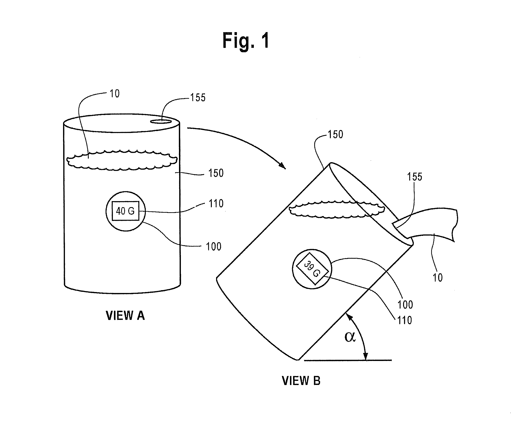
[0020]The present technology describes volumetric measuring devices and methods for monitoring the volume of fluid transferred from, and remaining in, a container. For example, a container, such as a 55-gallon drum, may contain an initial volume of fluid. Over time, the fluid may be poured from the drum to various other containers, vessels or to other locations. Certain embodiments of the present technology present a monitor for calculating the volume of water transferred from, and remaining, for example, within a 55-gallon drum based on the angle of tilt of the drum.

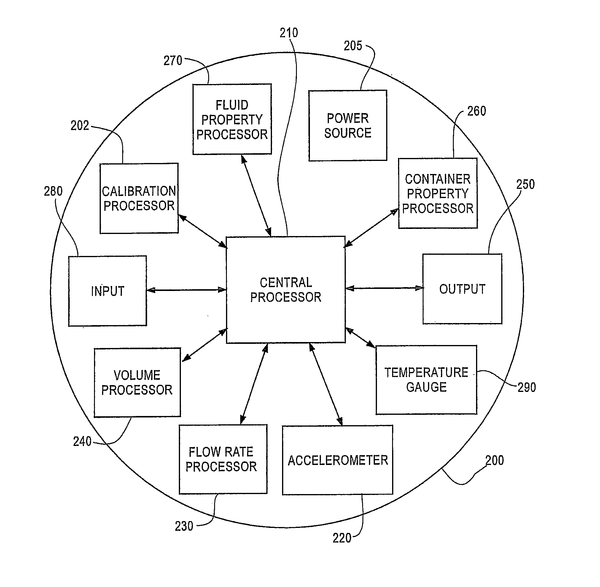
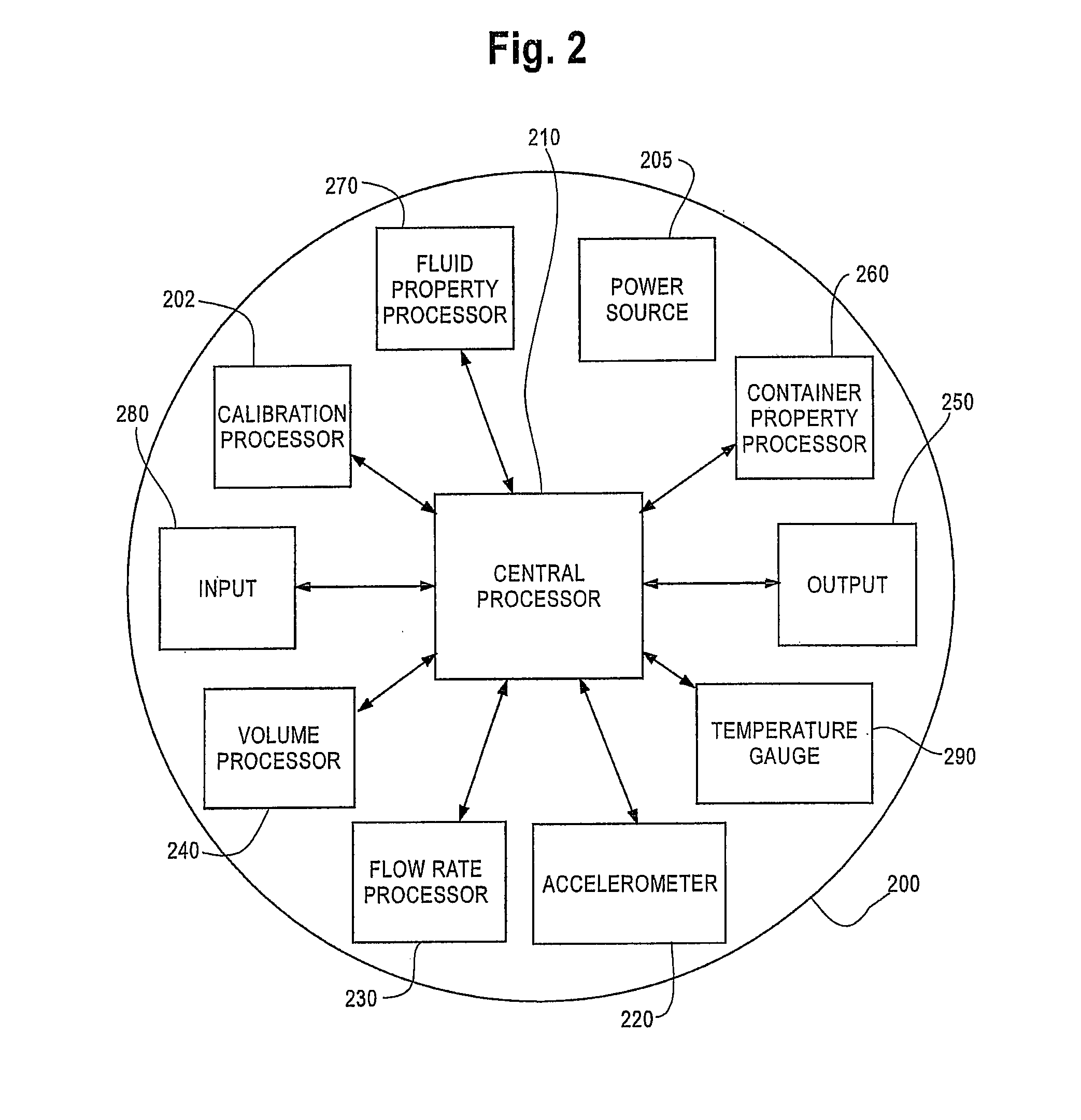
[0021]FIG. 1 depicts an embodiment of a monitor 100 monitoring the volume of fluid in a container 150. In View A of FIG. 1, the monitor 100 is attached to a container 150 holding a particular volume of fluid 10. A display 110 on the monitor 100 depicts a present value of volume of fluid within the container (“40 G”, or 40 gallons in View A). As the container is tipped at an angle of tilt, a, as shown in View B of FIG. 1...


PUM


Abstract

The present technology relates to a volumetric measurement device and various methods for operation of the device. The device comprises at least one accelerometer for detecting the angle of tilt / tip of a container. The device also comprises at least one fluid property processor capable of providing at least one fluidic property value of a fluid, a flow-rate processor capable of continuously calculating the present flow rate of the fluid when poured from the container, and a volume processor capable of continuously calculating the present volume of the fluid within the container. The flow-rate processor calculates the rate of flow of the fluid poured from the container based on the angle of tilt / tip of the apparatus, the at least one fluid property value, and the present volume of fluid within the container.

Description

RELATED APPLICATIONS[0001][Not Applicable]FEDERALLY SPONSORED RESEARCH OR DEVELOPMENT[0002][Not Applicable]MICROFICHE / COPYRIGHT REFERENCE[0003][Not Applicable]BACKGROUND OF THE INVENTION[0004]The present technology generally relates to one or more an apparati and methods for monitoring the quantity of fluid in a container. More specifically, the apparati relates to methods and devices that determine the quantity of fluid poured from a container in an enhanced precision manner based on the application of a mathematical algorithm to the angle of tilt of the container.[0005]Monitoring the amount of fluid transferred between vessels is an important practice in operations that involve frequent transfer of fluids. Auto repair shops, laboratories, plants, and even kitchens are frequently measuring the amount of fluid transferred between containers. For example, a chemical production facility may need to transfer a portion of fluid (e.g., one gallon) from a 55-gallon storage drum into a mix...

Claims


Application Information

Patent Timeline
Patent Type & Authority Patents(United States)
IPC IPC(8): G01F17/00
CPCG01F1/00G01F11/00
Inventor CEBULSKI, JAMES
Owner CEBULSKI DAVID W
Why Eureka
Try Eureka