Fuel injector diagnostic for dual fuel engine

a dual fuel engine and injector technology, applied in the direction of machines/engines, combustion air/fuel air treatment, electric control, etc., can solve the problems of insufficient and inability to accurately diagnose the actual amount of fuel injected to each cylinder of the engine, etc., to achieve the effect of increasing the variability of piece-to-piece injectors, reducing fuel

Active Publication Date: 2012-02-21
FORD GLOBAL TECH LLC
View PDF69 Cites 40 Cited by
  • Summary
  • Abstract
  • Description
  • Claims
  • Application Information

AI Technical Summary

Benefits of technology

[0002]When new, fuel injectors may exhibit some piece-to-piece variability. Over time, injector performance may degrade (e.g., injector becomes clogged) which may further increase piece-to-piece injector variability. As a result, the actual amount of fuel injected to each cylinder of an engine may not be the desired amount and the difference between the actual and desired amounts may vary between injectors. Such discrepancies can lead to reduced fuel economy, increased tailpipe emissions, and an overall decrease in engine efficiency. Further, engines operating with a plurality of different injection substances, such as different fuel mixtures, may have even more fuel injectors (e.g., twice as many) resulting in a greater possibility for degradation of engine performance due to injector degradation.
[0004]By suspending pumping in the second fuel rail, an injector can be isolated and pressure drops in the fuel rail can be correlated to the operation of the injector. Further, injection of the first fuel can continue without interruption in all but one of the cylinders. In this manner, each fuel injector can be isolated and tested without significantly affecting engine operation.

Problems solved by technology

Over time, injector performance may degrade (e.g., injector becomes clogged) which may further increase piece-to-piece injector variability.
As a result, the actual amount of fuel injected to each cylinder of an engine may not be the desired amount and the difference between the actual and desired amounts may vary between injectors.
Such discrepancies can lead to reduced fuel economy, increased tailpipe emissions, and an overall decrease in engine efficiency.
Further, engines operating with a plurality of different injection substances, such as different fuel mixtures, may have even more fuel injectors (e.g., twice as many) resulting in a greater possibility for degradation of engine performance due to injector degradation.

Method used


Image

  • Fuel injector diagnostic for dual fuel engine
  • Fuel injector diagnostic for dual fuel engine
  • Fuel injector diagnostic for dual fuel engine

Examples


Embodiment Construction

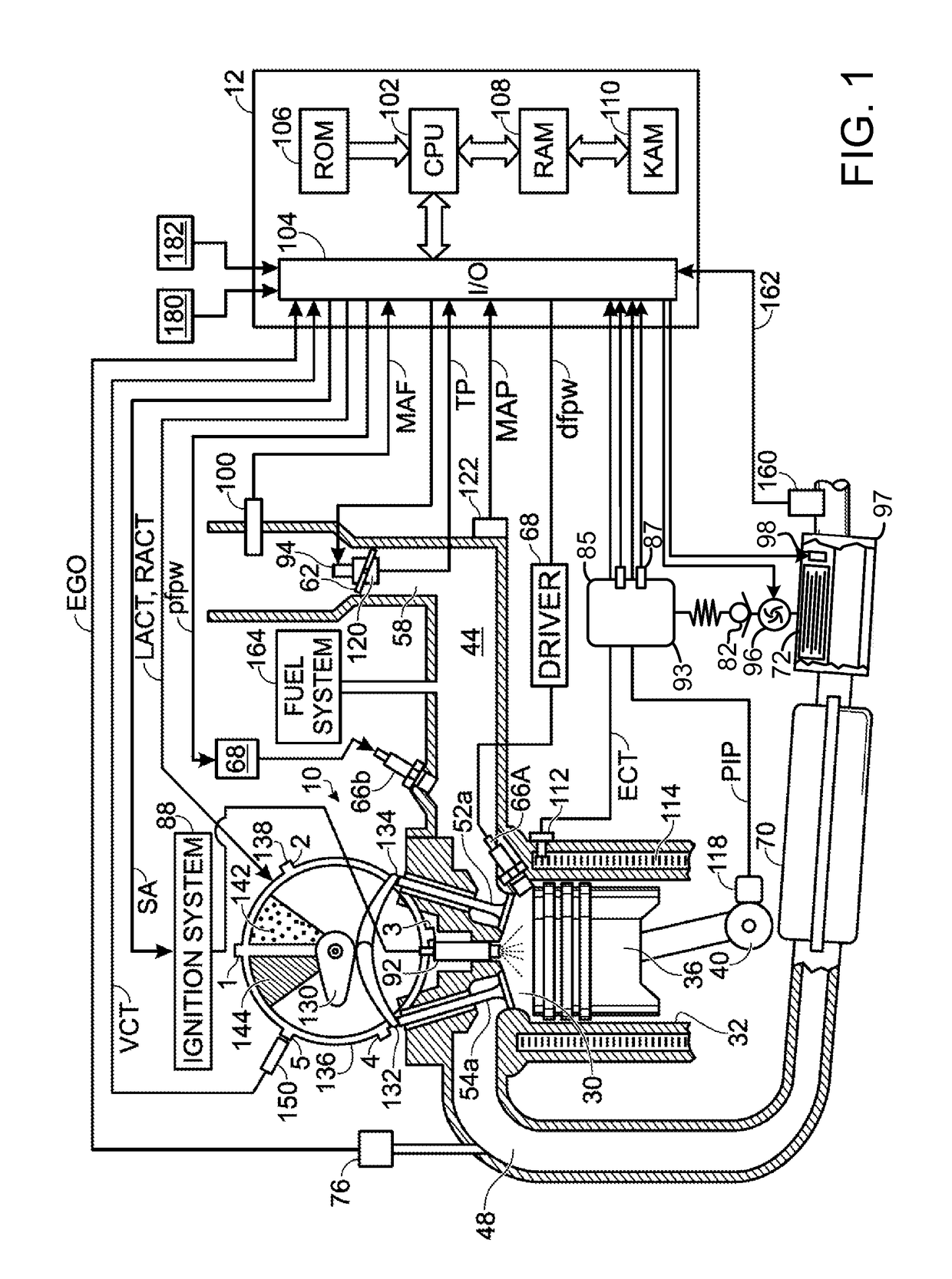
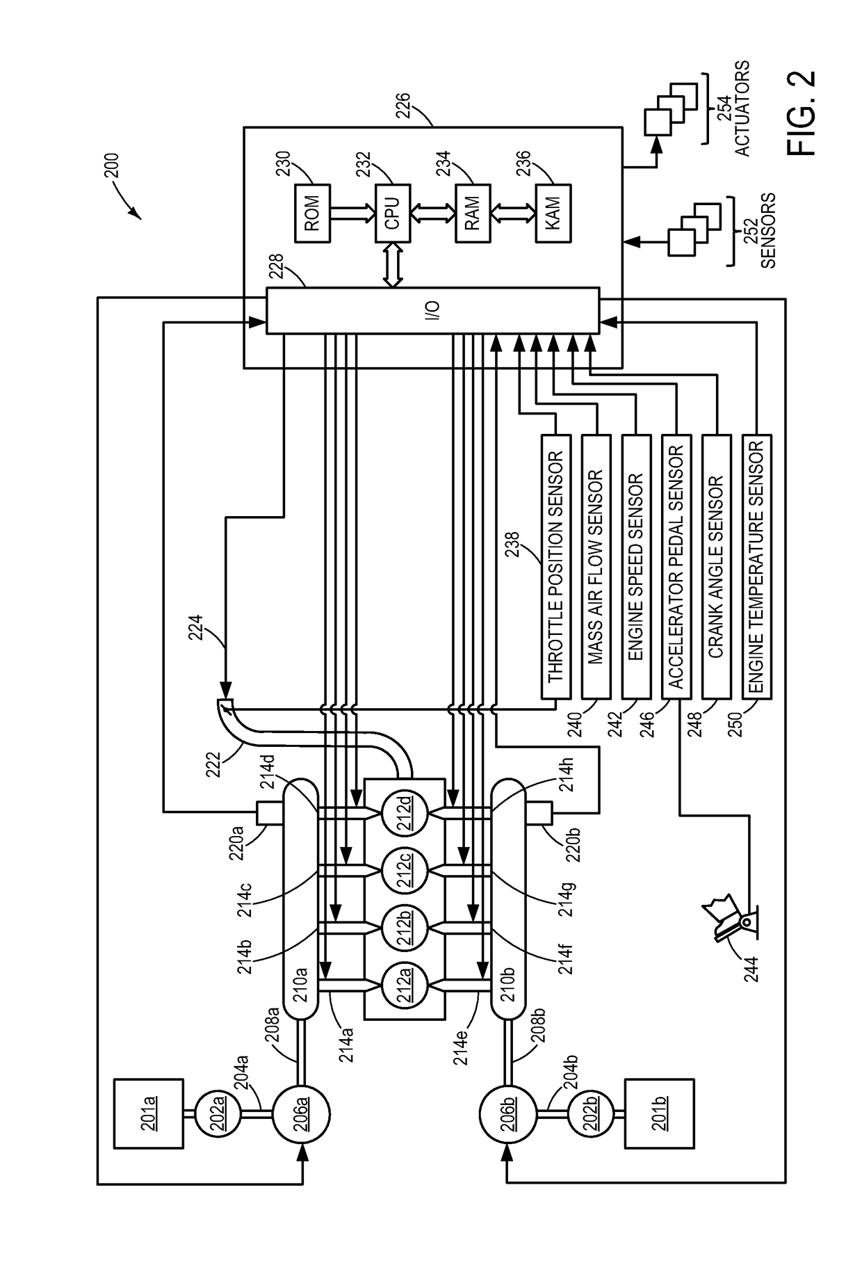
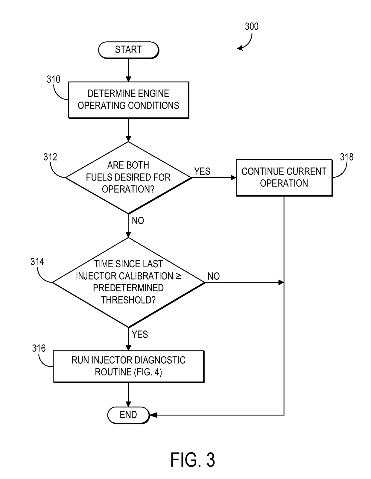
[0013]The following description relates to a method for controlling fuel injection in a multi-injection substance engine, such as a dual fuel engine, which includes first and second fuel rails and first and second fuel pumps. In one example, a diagnostic routine may be carried out in the following manner: pumping of a second fuel into the second fuel rail is suspended while a first fuel is injected to all but a single cylinder of the engine. Further, while pumping is suspended in the second fuel rail, the second fuel is injected into the single cylinder and the pressure decrease in the second fuel rail is correlated to injector operation. In this manner, a single injector may be isolated at one time allowing the injector to be tested without having a substantial impact on the performance of the engine. Furthermore, all injectors for both types of fuel can be tested in this manner. In another example, a sub-group of cylinders may be isolated together, rather than a single cylinder as...


PUM


Abstract

Various systems and methods are described for controlling fuel injection of a dual fuel engine which includes first and second fuel rails and first and second fuel pumps. In one example, while pumping is suspended in the second fuel rail, the first fuel is injected to all but one cylinder of the engine and the second fuel is injected to the one cylinder in a predetermined sequence. As such, the fuel injector injecting to the one cylinder is isolated and its performance may be assessed without significantly affecting engine performance.

Description

TECHNICAL FIELD[0001]The present application relates to diagnosing injector variability in a fuel injection system in a dual fuel engine.BACKGROUND AND SUMMARY[0002]When new, fuel injectors may exhibit some piece-to-piece variability. Over time, injector performance may degrade (e.g., injector becomes clogged) which may further increase piece-to-piece injector variability. As a result, the actual amount of fuel injected to each cylinder of an engine may not be the desired amount and the difference between the actual and desired amounts may vary between injectors. Such discrepancies can lead to reduced fuel economy, increased tailpipe emissions, and an overall decrease in engine efficiency. Further, engines operating with a plurality of different injection substances, such as different fuel mixtures, may have even more fuel injectors (e.g., twice as many) resulting in a greater possibility for degradation of engine performance due to injector degradation.[0003]The inventor herein has...

Claims


Application Information

Patent Timeline
Patent Type & Authority Patents(United States)
IPC IPC(8): F02B3/00F02M31/00F02M51/00F02B13/00
CPCF02D41/0027F02D41/0082F02D41/221F02D41/3845F02M69/046F02D19/061F02D19/0623F02M63/029F02D2041/224F02D2041/3881Y02T10/36F02D19/0628F02D19/0689F02D19/0692Y02T10/30
Inventor PURSIFULL, ROSS DYKSTRA
Owner FORD GLOBAL TECH LLC
Why Eureka
Try Eureka