Magnetic valve

a magnetic valve and valve body technology, applied in the field of magnetic valves, can solve the problems of difficult calibration of the magnetic valve, limit the further development of the integration of parts in the optimizing valve assembly, etc., and achieve the effect of reducing the magnetic flux, increasing the magnetic flux, and being easy to calibrate and adjus

Inactive Publication Date: 2012-02-28
ROBERT BOSCH GMBH
View PDF19 Cites 15 Cited by
  • Summary
  • Abstract
  • Description
  • Claims
  • Application Information

AI Technical Summary

Benefits of technology

[0008]The magnetic valve of the invention has the advantage over the prior art that a sealing seat is disposed in a sleeve which is fitted into a capsule and has at least one opening, through which adjusting elements act on a valve insert for adjusting a magnetic flux generated by a magnet assembly. As a result, an air gap between the valve insert and an armature can be varied, and the adjusting elements move the valve insert axially toward the armature to increase the magnetic flux or move the valve insert axially away from the armature to decrease the magnetic flux. The adjusting elements according to the invention, which act via existing openings on the poorly accessible components, that is the valve insert, advantageously make it possible for even magnetic valves with components fitted into one another in sleevelike fashion to be easily calibrated and adjusted for function without major additional effort or expense. The invention makes use of the geometric properties, created by functional integration, of the magnetic valve so as to advantageously enable the calibration and function adjustment even via poorly accessible internal components.
[0009]It is especially advantageous that the capsule is wedged with a valve bush in a wedging region with a fluid block, thereby greatly simplifying the valve insert. For adjusting the air gap between the valve insert and the armature, a tappet dips sealingly into the sealing seat of the sleeve; that is, the sealing seat of the sleeve is closed during the calibration process.
[0012]In a further feature of the magnetic valve of the invention, at least one adjusting element can be introduced into the sleeve radially through at least one opening and acts, axially guided, on the valve insert. Alternatively, the at least one radially introduced adjusting element can act in a rotationally leverlike fashion on the valve insert.
[0011]In a further feature of the magnetic valve of the invention, at least one adjusting element is solidly connected to the valve insert and acts on the valve insert through a first opening, and the at least one adjusting element, after the adjustment of the air gap, can be disconnected from the valve insert by means of a tool, for instance by means of a cutting tool, introduced through a second opening. Alternatively, at least one adjusting element can be embodied as a pair of grippers which can be introduced axially into the sleeve through two openings and acts axially on the valve insert.

Problems solved by technology

For the adaptation, the moving components should be readily accessible, which can limit further development of the integration of the parts in optimizing valve assemblies.
Because the components are fitted into one another in sleevelike fashion, however, calibrating the magnetic valve is difficult to do.

Method used


Image

  • Magnetic valve
  • Magnetic valve
  • Magnetic valve

Examples


Embodiment Construction

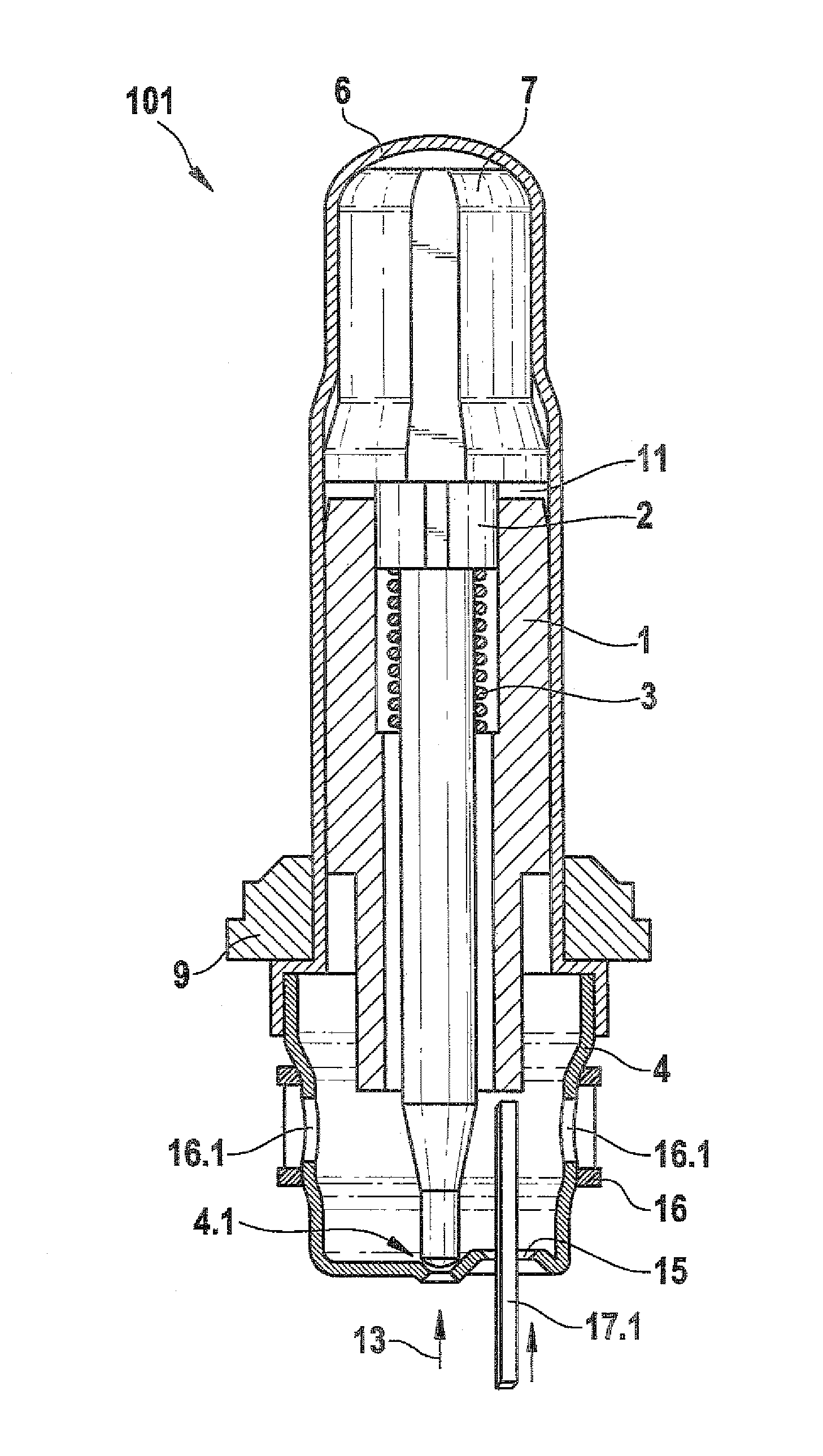
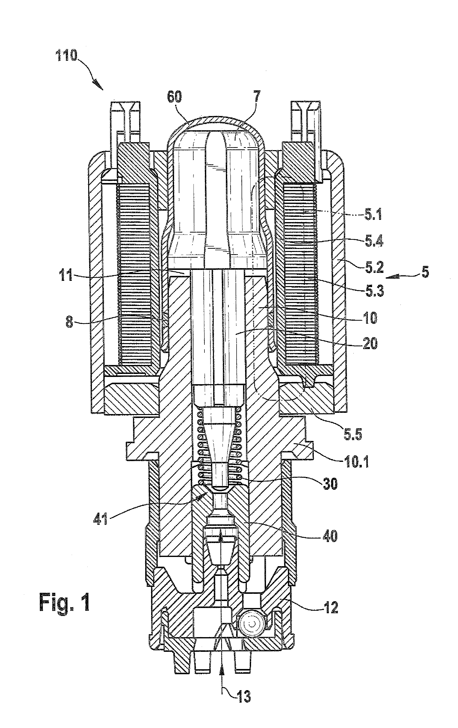
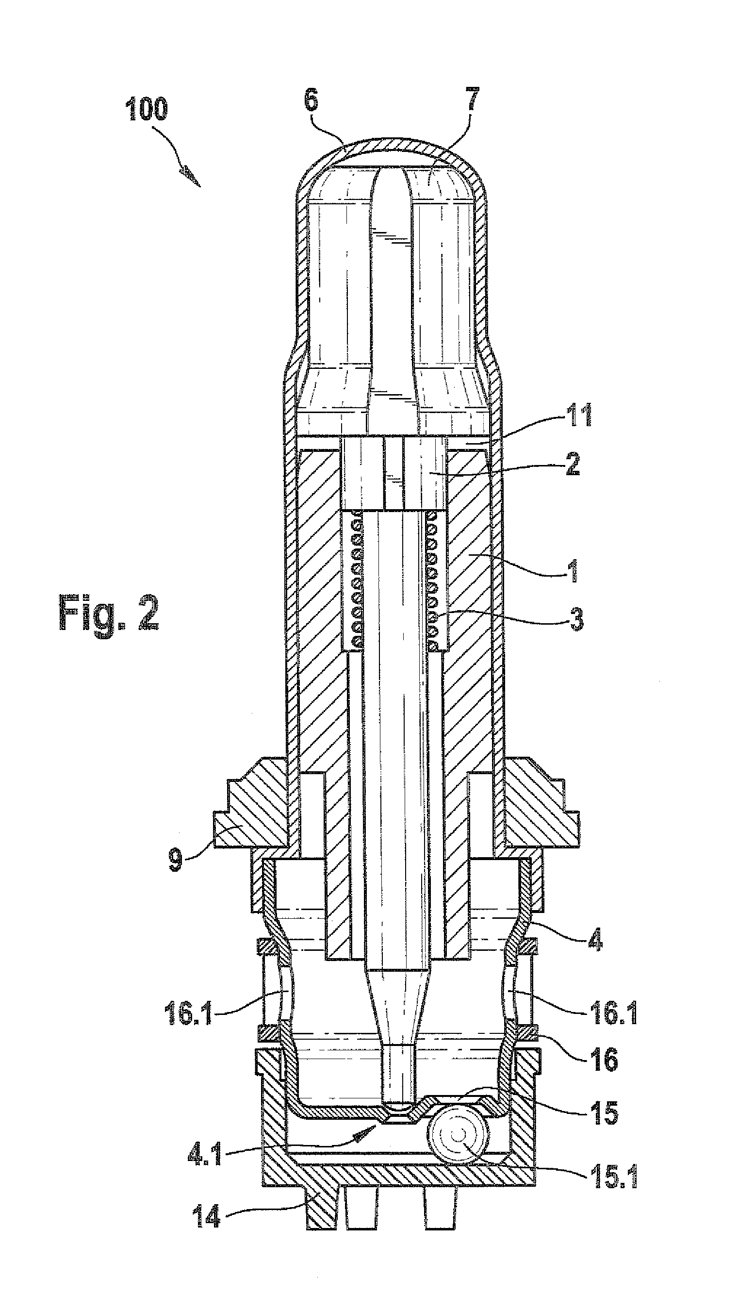
[0020]As can be seen from FIG. 2, a valve cartridge 100 for a magnetic valve according to the invention, which valve cartridge is wedged via a valve bush 9 in a wedging region, not shown, with a fluid block, includes a capsule 6, a sleeve 4, a valve insert 1, a tappet 2 guided in an inner bore of the valve insert 1, a restoring spring 3 which is braced against the valve insert 1 in the inner bore and restores the tappet 2, and an armature 7. The capsule 6 is pushed in overlapping fashion onto the valve insert 1 and is embodied as a valve component that provides sealing from the atmosphere. In a distinction from the conventional magnetic valve 110 shown in FIG. 1, the capsule 6 is lengthened in the direction of the wedging region. As a result, the conventional sealing weld 8 of FIG. 1 can be omitted. Furthermore, the fluid forces and wedging forces are no longer absorbed by the valve insert 1 but rather by the valve bush 9 and are transmitted to the fluid block via the wedging region...


PUM


Abstract

The invention relates to a magnetic valve having a magnetic assembly and a capsule. An armature is disposed in the capsule and a valve insert is inserted in the capsule. A tappet is guided in a displaceable manner within the inner bore of the valve insert and sealingly immerges in a sealing seat. The valve insert is arranged at a distance from the armature via an adjustable air gap. According to the invention, the sealing seat is arranged in a sleeve which itself is disposed inside the capsule. The sleeve has at least one opening through which adjusting elements act upon the valve seat in order to regulate the magnetic flux generated by the magnetic assembly. The air gap between the valve insert and the armature is variable, whereby the adjusting elements either move the valve insert in axial direction towards the armature in order to increase the magnetic flux or move the valve insert away from the armature in order to reduce the magnetic flux.

Description

CROSS-REFERENCE TO RELATED APPLICATION[0001]This application is a 35 USC 371 application of PCT / EP 2006 / 069222 filed on Dec. 1, 2006.BACKGROUND OF THE INVENTION[0002]1. Field of the Invention[0003]The invention is based on a magnetic.[0004]2. Description of the Prior Art[0005]A conventional magnetic valve, particularly for a hydraulic unit, which is used for instance in an anti-lock brake system (OBOIST) or traction control system (TCS) or an electronic stability program system (ESP system), is shown in FIG. 1. As can be seen from FIG. 1, the conventional magnetic valve 110 includes a magnet assembly 5 for generating a magnetic flux 5.1, which magnet assembly in turn includes a housing 5.2, a coil winding 5.3, a coil body 5.4, and a covering disk 5.5; and a valve cartridge, which includes a capsule 60, a valve insert 10, a tappet 20, a restoring spring 30, and an armature 7. In the production of the magnetic valve 110, the capsule 60 and the valve insert 10 of the valve cartridge ar...

Claims


Application Information

Patent Timeline
Patent Type & Authority Patents(United States)
IPC IPC(8): F16K31/02
CPCB60T8/363H01F7/126F16K31/0675F16K31/0658Y10T137/0491Y10T137/0486
Inventor KRATZER, DIETMAR
Owner ROBERT BOSCH GMBH
Why Eureka
Try Eureka